

Short answer
LV feeder voltage sensitivity depends on the actual current paths, impedance and operating point. Active power can strongly affect voltage on a resistive feeder, while reactive power has a different influence through reactance. A local approximation helps explain those effects, but its result is conditional. State the power direction, voltage basis and network assumptions before using a sensitivity value to evaluate PV export or reactive-power support.
Keep the power and voltage bases consistent
Consider a balanced three-phase feeder with per-phase route impedance R + jX and fixed source voltage. Let P and Q be total three-phase power flowing toward the receiving end: consumption and absorbed reactive power are positive, while export and reactive injection are negative. V is line-to-line RMS voltage. For small voltage drops and angle differences, the approximate receiving voltage is:
Vrecv ≈ Vsource − (RP + XQ)/V
Using per-phase power in this expression would introduce a factor-of-three error. A single-phase circuit requires its own voltage and complete return-path impedance. An explicit neutral model is needed where phase unbalance and neutral displacement materially affect customer voltages.
An illustrative export case
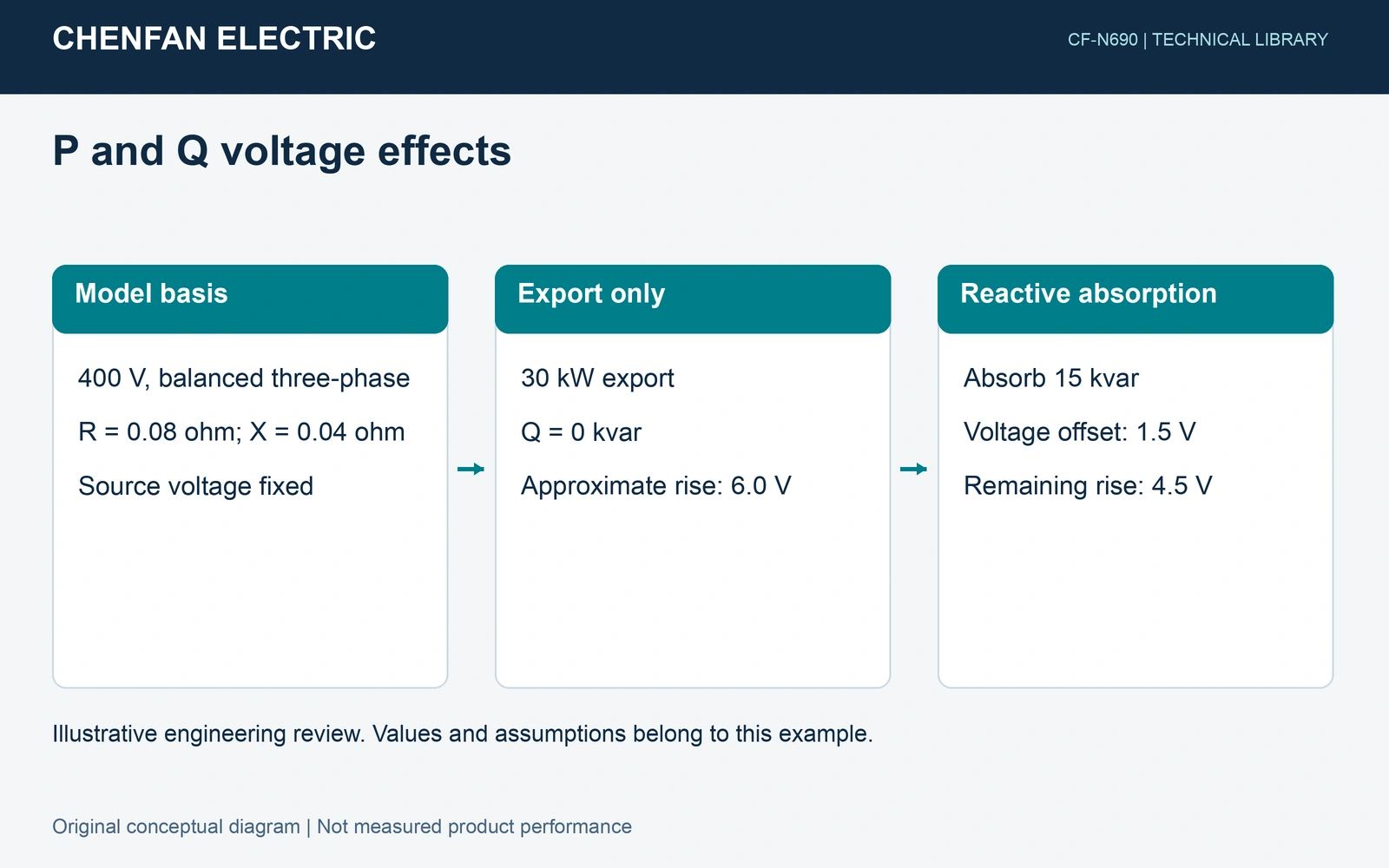
Assumptions. V = 400 V, R = 0.08 Ω and X = 0.04 Ω per phase over the complete route. The system is balanced, the source remains fixed, and losses and second-order terms are neglected. These are synthetic values.
At P = −30,000 W and Q = 0, the predicted voltage rise is 6.0 V, or 1.5% of 400 V. If the inverter instead absorbs 15,000 var, the reactive term offsets 1.5 V, leaving approximately 4.5 V rise. This comparison illustrates a mechanism; neither value establishes an allowed operating limit.
| Change | Approximate response |
|---|---|
| Additional consumption | −0.20 V per kW |
| Additional absorbed reactive power | −0.10 V per kvar |
| Export increase of 30 kW | +6.0 V with Q unchanged |
Check whether the local approximation remains useful
Changing source voltage, tap position, feeder topology or the distribution of generation changes the comparison. A resistance value also needs a temperature basis. Distributed loads require section currents rather than treating every customer as one end load.
The original linear-power-flow research by Marković and Hodge discusses the dependence of approximate voltage solutions on operating conditions. Its parameterized model is more extensive than the screening calculation here. This article does not implement that model or inherit its reported performance.
Turn sensitivity into a study input
Compare a small P or Q perturbation around the chosen operating point with a complete load-flow result. Record the affected node, phase, tap and source state. Repeat at credible demand and generation extremes, keeping inverter current and apparent-power limits. A voltage constraint at one customer can remain even when the transformer bus looks satisfactory.
Use the sensitivity to explain and rank candidate measures. Confirm the final operating envelope through the appropriate balanced or unbalanced network model, measured voltage at each node, and the applicable project criteria. A simple coefficient does not guarantee hosting capacity or unlimited reactive-power correction.
Sources and scope
- M. Marković and B.-M. Hodge, Parameterized Linear Power Flow for High Fidelity Voltage Solutions in Distribution Systems, original author preprint, arXiv:2209.04508v1, 2022.