

Adaptive protection must follow the electrical state of a reconfigured feeder, rather than select a relay group solely from a topology label. A changed source path can alter the current seen by each current transformer (CT), fault direction, protection boundaries and the minimum detectable fault. The design needs an approved relationship between actual network conditions and the protection functions that remain valid during and after the transition.
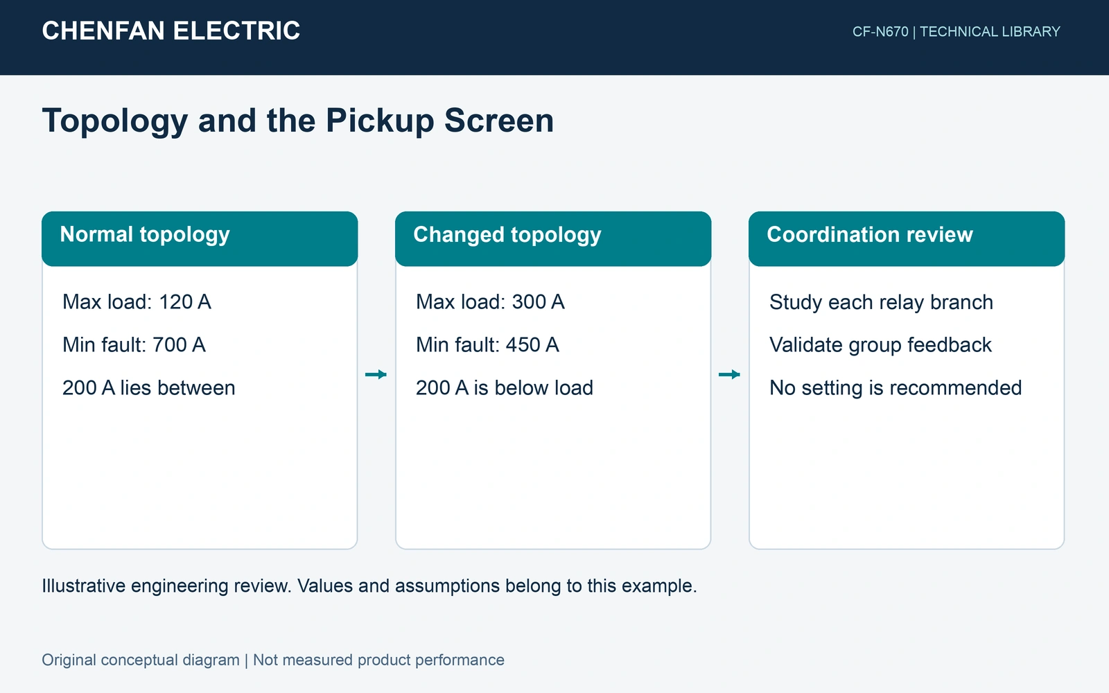
Build a state matrix before changing groups
Feeder reconfiguration for loss reduction and restoration can produce different source strengths and current paths. List normal supply, alternate supply, relevant outages, DER operating modes and any permitted island. For every state, identify each relay’s CT location, current reference, voltage polarization and protected zone. A fault current reported at the fault point is not automatically the current through an upstream relay.
An SEL industrial-network paper describes topology-dependent protection changes and logic that verifies the relays have the required settings group. Its demonstrated system was a 115 kV network, not a universal distribution-feeder recipe. The transferable principle is to confirm the active protection state, not merely send a group-change command. [1]
Use a pickup window as a preliminary screen
Consider synthetic primary-equivalent currents at one CT. In the normal state, assume maximum load of 120 A and minimum relevant fault current of 700 A. A hypothetical 200 A pickup lies between them. After transfer, assume maximum load rises to 300 A while minimum fault current falls to 450 A. The same pickup is now below the assumed load, although it still lies below the fault current.
The inequality I_max_load < I_pickup < I_min_fault is an independent screening construct here. It does not select a new setting. Real margins must account for overload and starting duty, measurement error, fault resistance, CT behavior and the required operating time. An inverse-time element may tolerate some temporary load above pickup, so duration and curve shape also require review. Even a nonempty interval does not prove selectivity with downstream fuses or upstream backup protection.
| State | Maximum load | Minimum fault | Hypothetical 200 A pickup |
|---|---|---|---|
| Normal | 120 A | 700 A | Between load and fault |
| Transfer | 300 A | 450 A | Below the assumed load |
Separate inverter modes from conventional sources
Check for protection blinding when downstream sources share a fault. Inverter current magnitude, duration and sequence behavior depend on hardware, firmware, controls and the connection. SEL’s inverter-distribution study addresses a particular project with different grid-connected and islanded protection needs. Its stated current capability must not become a fixed multiplier for every inverter. [2]
Validate transitions and failure states
Define what happens when switch status disagrees, a message is stale, one relay does not acknowledge a change or the topology is outside the approved matrix. Temporary states need their own protection assessment. A conservative group is useful only if its security and sensitivity have been checked for that state; the word conservative is not a substitute for evidence.
The procurement package should include the topology matrix, branch-current study, relay and firmware identities, CT/voltage-transformer data, time-current coordination results, group-selection interfaces and test responsibilities. Engineers responsible for protection approve the settings and transition logic. Factory and commissioning tests should retain group feedback, trip logic and failure results. Transformer supply or a relay’s setting-group feature alone does not provide that system-level approval.