

Loadbreak versus deadbreak connectors should be selected by their documented operating function and matched interface, not by the transformer’s load current alone. A continuous-current rating describes carrying duty; it does not establish an interruption rating. Likewise, a deadfront arrangement does not prove that every connection can be operated while energized. The enquiry needs the actual connector, bushing and accessory combination, together with the manufacturer’s permitted service conditions.
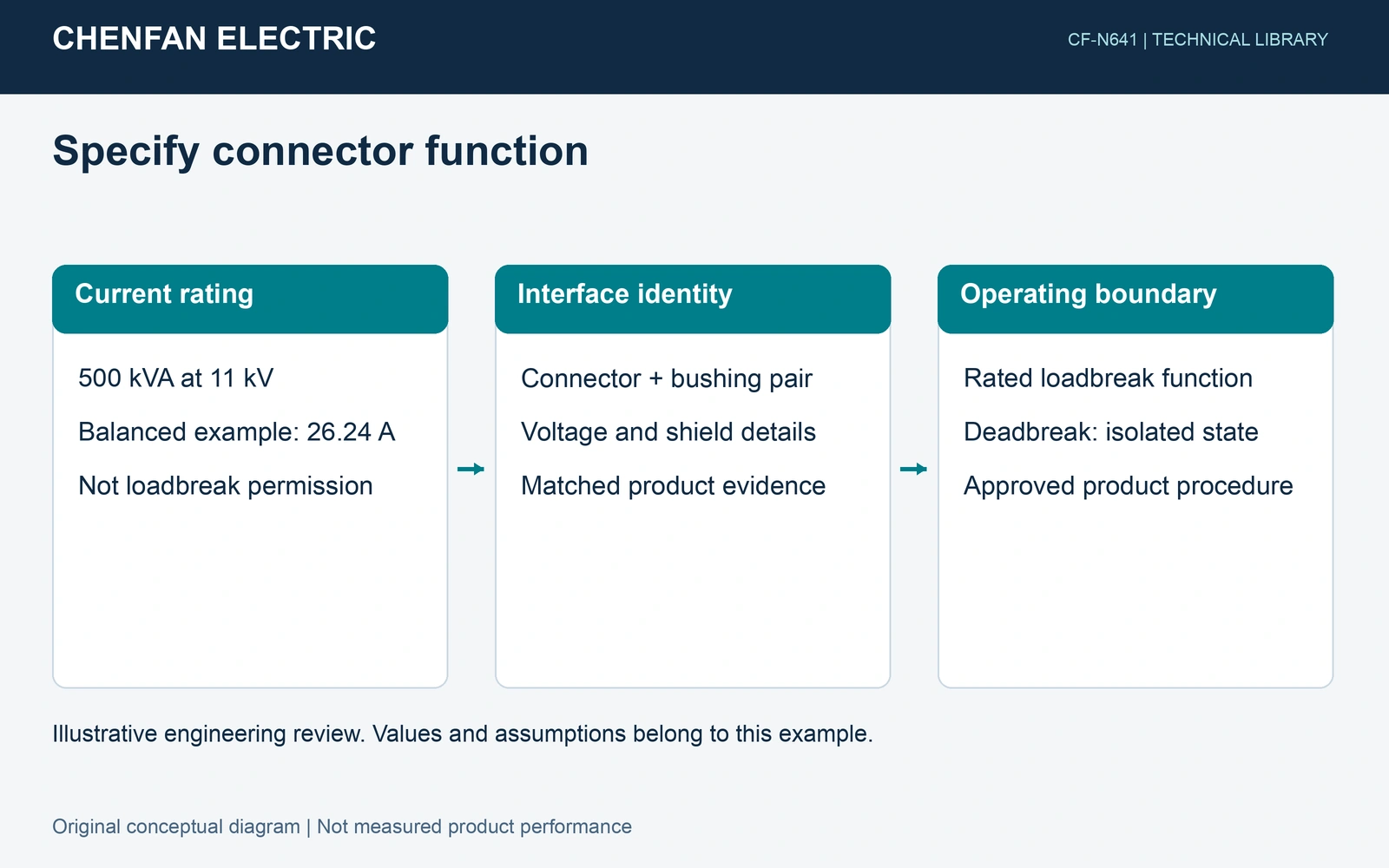
Separate carrying, switching and insulation duties
Eaton’s transformer fundamentals distinguish loadbreak and deadbreak categories among deadfront separable connectors. Its examples are product families, not a universal catalogue of interchangeable interfaces. A selected loadbreak system must have a stated ability to make or interrupt the specified load under its approved conditions. Fault making, short-time withstand, voltage class and continuous current remain separate fields. [1]
A deadbreak interface is not assigned a load-interruption function merely because the circuit carries little current. Its connection or separation requires the isolated, de-energized condition and verification required by the responsible manufacturer and site procedures. This distinction identifies a design boundary; it provides no energized-operation sequence or permission to improvise one.
A current calculation answers a narrower question
Assume a balanced three-phase transformer rated 500 kVA at 11 kV line-to-line, with sinusoidal rated current. The primary current is I = 500 / (√3 × 11) = 26.24 A. This is a carrying-duty input. It contains no contact-interruption test, fault-current value, interface qualification or operating assessment. Even a measured current below this example cannot convert a deadbreak connection into a loadbreak one.
| Field | Evidence to retain | Boundary |
|---|---|---|
| Continuous current | Named assembly rating | Does not prove load interruption |
| Switching duty | Applicable making/breaking ratings | Not inferred from measured current |
| Insulation/interface | Matched connector and bushing data | No visual interchangeability claim |
| Water and support | Installed boundary drawings | Cable feature is not enclosure approval |
Specify the assembled interface
Record both sides of the connection: connector designation, bushing or insert designation, interface dimensions, conductor size range and shield/earthing arrangement. Ask which combinations the suppliers approve and which qualification evidence covers that combination. Similar appearance or a shared nominal voltage is insufficient. Cable preparation, mechanical support and operating-tool requirements also belong to the selected product’s documentation, without publishing generic installation steps.
Document the installed cable-entry boundary separately. Prysmian’s cable construction information distinguishes barriers along a cable from barriers through its layers; those features do not qualify the connector assembly or transformer compartment. Water-blocking, connector sealing and compartment drainage therefore need their own evidence and assigned responsibility. [2]
Release a function-based specification
Retain the agreed interface drawings and rating schedule with the transformer order. The equipment OEM and system designer must confirm how the completed arrangement meets the project’s operating, protection and environmental requirements. A transformer-core dimensional report cannot validate connector switching duty. The useful purchasing result is a traceable matched assembly with clearly stated operating limits, rather than a connector description chosen from current rating alone.
References and scope
- Medium-voltage transformers: fundamentals of medium-voltage transformers
- 15-46kV EPR TRIPLESEAL™ Cable (US) | Prysmian
Sources support the stated mechanisms and application boundaries. Product data remain specific to the named design; illustrative arithmetic is not a project approval or operating instruction.