


Transformer Core Engineering Notes · CF-N286
A transformer supplied with wheels still needs a precisely coordinated rail interface. Gauge, wheel orientation, support reactions, elevation and movement direction should be agreed before rails are installed. The aim is not merely to make the equipment sit on the track, but to provide the approved support and movement arrangement without forcing the transformer into an incompatible civil layout.
Define gauge and orientation unambiguously
State the dimension reference used for the wheel gauge and the intended direction of movement. Some designs allow wheel orientation changes, but the permitted arrangement and procedure must come from the OEM. Do not assume that a wheel can be rotated or repositioned under load. Coordinate the wheel centers, rail centers and drawing axes so terminology differences do not produce a civil installation error.
Coordinate support reactions and elevations
The civil designer needs the applicable wheel or support loads and the required rail geometry. Uneven support can change load distribution, so use OEM-defined tolerances and qualified structural design rather than a guessed leveling allowance. Identify transitions between temporary movement arrangements and final supports. A transformer that reaches its intended position still needs a verified final support condition.
Plan restraint and movement boundaries
The final arrangement may require restraints or anchorage for the applicable operating loads. These are not automatically provided by wheels resting on rails. The OEM and civil designer should define the accepted restraint system and its effect on movement and load transfer. This article does not prescribe wheel stops or anchorage dimensions; those details must be engineered for the project and installation state.
Freeze and verify the interface
Issue a coordinated drawing showing gauge, elevations, movement direction, loads and responsibility for installation checks. Reconcile equipment revisions before the rail layout becomes difficult to change. The as-built survey should be assessed against the approved requirements before movement or placement. Keeping this interface controlled avoids field alterations that might compromise support, clearance or the intended handling arrangement.
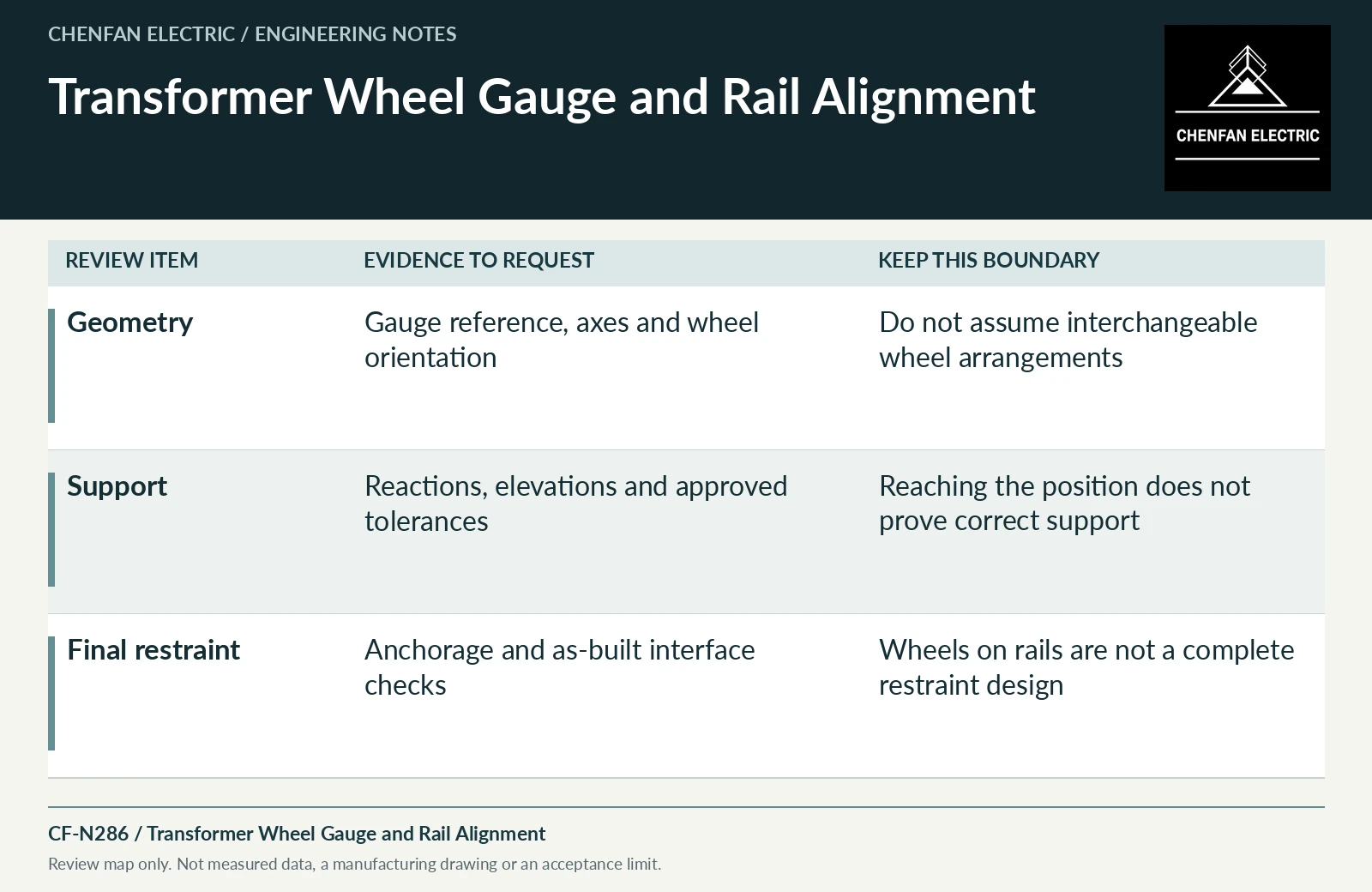
| Review item | Evidence to request | Boundary to preserve |
|---|---|---|
| Geometry | Gauge reference, axes and wheel orientation | Do not assume interchangeable wheel arrangements |
| Support | Reactions, elevations and approved tolerances | Reaching the position does not prove correct support |
| Final restraint | Anchorage and as-built interface checks | Wheels on rails are not a complete restraint design |
References and scope
- IEC 60076-1:2011 — Power transformers: GeneralPublic standard abstract · General transformer scope, interfaces and controlled equipment specification.
- Dry-Type Transformers 1000 Volts and Below — Instruction Bulletin 43006-850-01Manual listing / metadata only · Example of why handling and installation instructions must match the actual product and voltage range.