


Transformer Core Engineering Notes · CF-N287
A bus duct is both an electrical connection and a mechanical system. Its weight, support layout, thermal movement and fault response can impose loads on transformer terminals. The bus-duct designer and transformer OEM should agree the interface forces, displacements and tolerances before fabrication, rather than treating the terminal as a convenient fixed support.
Identify the load sources
Separate dead weight, installation misalignment, thermal expansion and applicable dynamic or fault loads. They may act in different directions and combinations. The complete bus support arrangement determines how much reaches the transformer. A short connecting section is not automatically lightly loaded if its upstream supports constrain movement. Ask for the calculated interface actions under the project-defined load cases.
Obtain terminal limits in a shared coordinate system
The OEM should identify allowable forces, moments and movement for the actual terminal or bushing arrangement, with the relevant conditions. The bus supplier’s output must use compatible axes and reference points. A force applied at an offset can create a moment that is missed by comparing force magnitudes alone. Keep the interface data explicit enough for both designers to assess the same physical connection.
Assess flexible elements as engineered components
A flexible connector can accommodate specified movement, but it still has stiffness, current capacity and mechanical limits. Its orientation and installed shape matter. Do not assume it transfers no force or can absorb unlimited misalignment. Coordinate the selected component and support spacing with the electrical clearances and OEM terminal limits rather than choosing it only from a conductor cross-sectional area.
Check the as-installed alignment
Survey the final terminal and bus positions before completing the connection under the approved procedure. Do not pull a misaligned bus into place using the transformer terminal. Record deviations and obtain the designers’ disposition. The accepted interface should include final support locations and any approved adjustments so future maintenance does not accidentally remove a support essential to keeping terminal loads within limits.
| Review item | Evidence to request | Boundary to preserve |
|---|---|---|
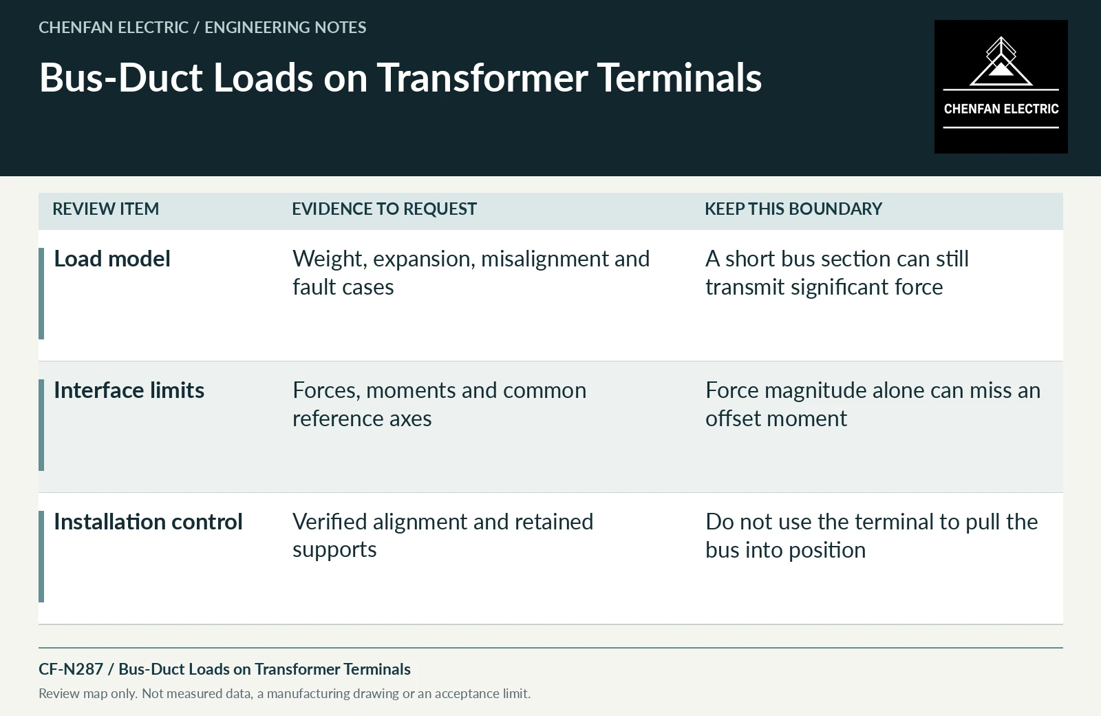
| Load model | Weight, expansion, misalignment and fault cases | A short bus section can still transmit significant force |
| Interface limits | Forces, moments and common reference axes | Force magnitude alone can miss an offset moment |
| Installation control | Verified alignment and retained supports | Do not use the terminal to pull the bus into position |
References and scope
- Bushing Maintenance (FIST 3-2)Historical technical manual · Bushing components, connection and maintenance interfaces.
- Electrical Connections for Power Circuits (FIST 3-3)Historical technical manual · Electrical-joint and connection principles; not a universal torque table.
- IEC 60076-1:2011 — Power transformers: GeneralPublic standard abstract · General transformer scope, interfaces and controlled equipment specification.