


Transformer Core Engineering Notes · CF-N289
An installation is not fully serviceable just because the transformer can be delivered once. Future replacement may occur after walls, adjacent equipment and overhead services are complete. Review the removal route, handling state and temporary works before accepting the layout, and keep replacement access distinct from the normal operating footprint.
Define the assembly to be removed
Specify whether replacement means moving the complete transformer or an OEM-approved reduced configuration with designated accessories removed. Record the resulting dimensions, mass and center of gravity. Do not assume that bushings, radiators or structural members can be removed simply to fit a doorway. Any dismantling and reassembly must follow a supported product-specific plan and preserve the equipment’s required condition.
Check the entire three-dimensional route
Door openings, turns, thresholds, overhead services and temporary handling equipment all consume space. A clear width at one doorway does not prove the route is passable. Include the swept envelope during turns and the height required by the approved handling arrangement. The route study should use the final building geometry, not just the unfinished shell available during first delivery.
Verify loads and temporary works
Floors, covers and temporary supports must be assessed for the actual handling loads by qualified structural engineers. A slab suitable for normal distributed service loads may not automatically suit concentrated movement reactions. Identify any removable roof panels or walls and the engineering needed to use them. This article does not authorize handling over an unverified floor or prescribe a generic replacement method.
Keep the route available over the asset life
Record replacement access as a controlled building interface so later cable trays, storage or equipment additions do not block it. Identify outages and temporary relocations that the replacement plan assumes. A low-cost initial layout can create a costly future dependency if those assumptions are invisible. The owner should receive a route drawing and responsibility list that can be checked whenever the surrounding installation changes.
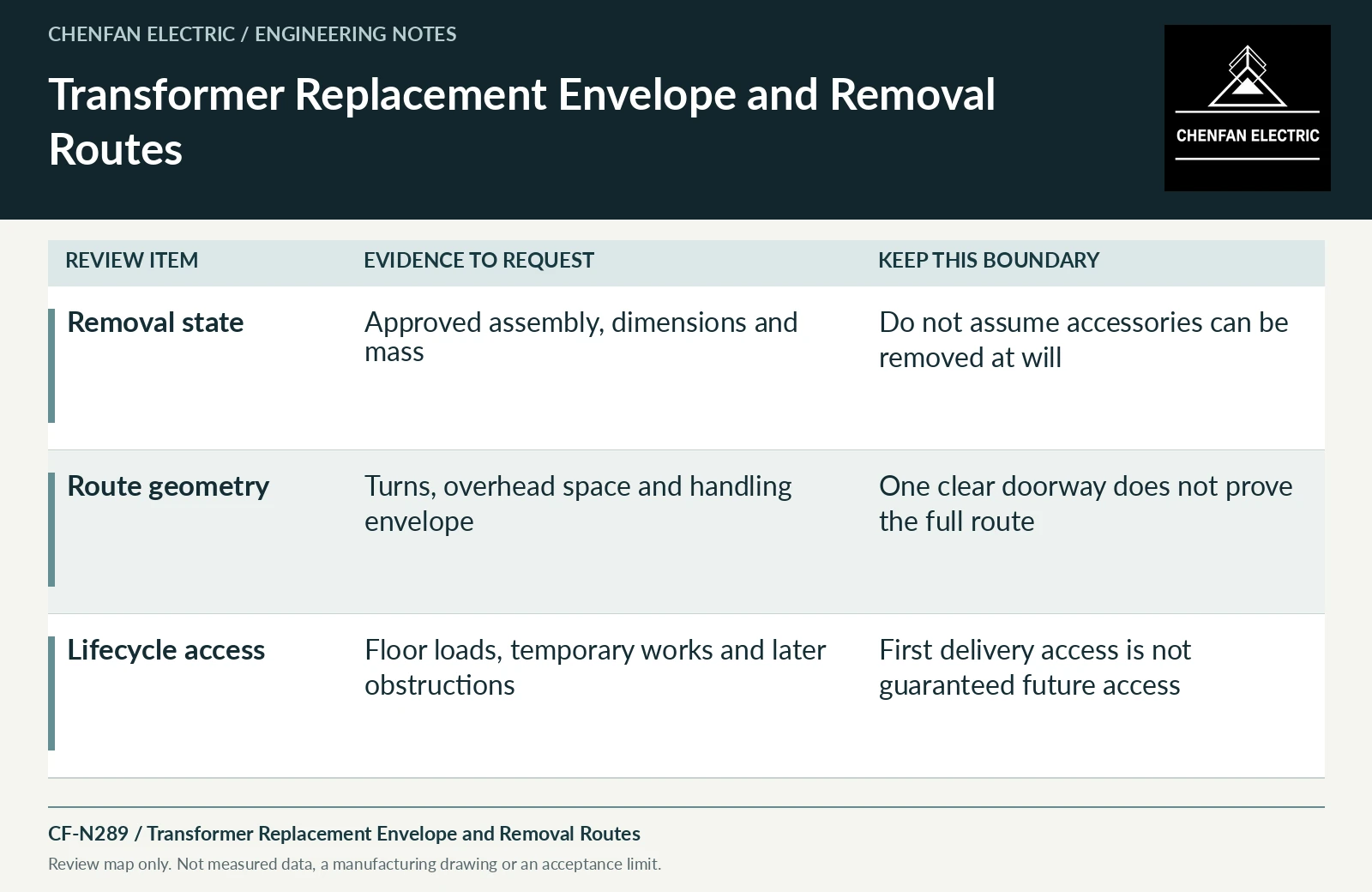
| Review item | Evidence to request | Boundary to preserve |
|---|---|---|
| Removal state | Approved assembly, dimensions and mass | Do not assume accessories can be removed at will |
| Route geometry | Turns, overhead space and handling envelope | One clear doorway does not prove the full route |
| Lifecycle access | Floor loads, temporary works and later obstructions | First delivery access is not guaranteed future access |
References and scope
- IEC 60076-1:2011 — Power transformers: GeneralPublic standard abstract · General transformer scope, interfaces and controlled equipment specification.
- Dry-Type Transformers 1000 Volts and Below — Instruction Bulletin 43006-850-01Manual listing / metadata only · Example of why handling and installation instructions must match the actual product and voltage range.