


Transformer Core Engineering Notes · CF-N209
A tapping section changes more than the turns ratio. Different tap positions can change active turns, current distribution, local losses and the lead arrangement carrying load current. Review the regulating winding, its connections and the tap-changing equipment as one coordinated circuit, while keeping their individual design and test responsibilities identifiable.
Name the states that the project will use
Specify the required ratio range, step arrangement, operating currents and whether changing taps is permitted under load. On-load and de-energized tap-changing duties are not interchangeable. Identify any operating restrictions and the expected control mode. The OEM should then state which tap positions govern thermal, dielectric and short-circuit checks. The principal tap may be convenient for a datasheet, but it cannot be assumed to represent every limiting condition.
Track inactive sections and connection geometry
A section that does not carry the main load current in one tap state is not automatically irrelevant to insulation or transient behaviour. Its electrical potential and coupling depend on the circuit. Request an unambiguous connection diagram showing the selected and unselected paths. Routing changes must also preserve required support and clearances around the winding ends. A lead label on an outline drawing is not enough to establish this internal arrangement.
Check the small regions that can run hot
Tap leads, joints and selected contact paths may have a different thermal environment from the main winding. Compare their current duty with the actual cooling and connection design. Total load loss does not identify the temperature of every joint. Ask how local heating is addressed and which temperature or loss evidence applies. If the tap range is extended, review the winding and lead design again instead of only changing the tap-changer ordering code.
Control the cross-supplier handover
The transformer OEM and tap-changer supplier need consistent current, voltage and operating-duty information. Record connection identification, interface dimensions and the responsibility for functional checks. Any separated oil compartment also needs its own filling and monitoring boundary where applicable. Before release, reconcile the winding drawing, tap table, control description and nameplate data. Agreement on rated power alone will not expose a mismatch between the selected winding section and the control indication.
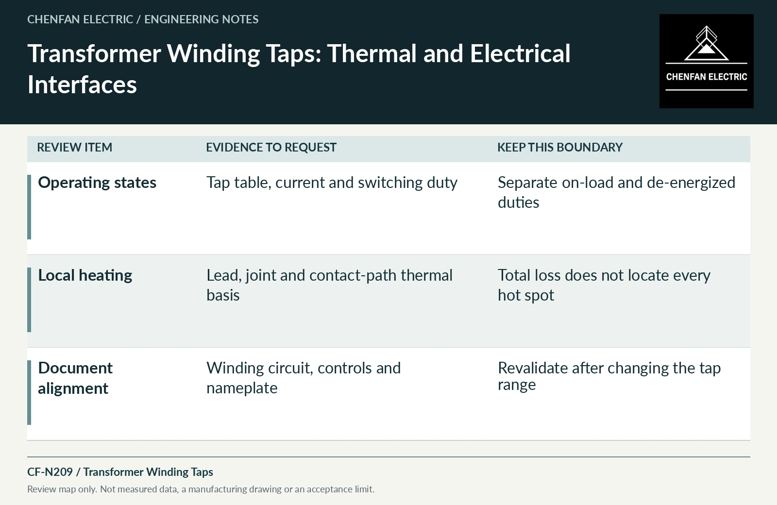
| Review item | Evidence to request | Boundary to preserve |
|---|---|---|
| Operating states | Tap table, current and switching duty | Separate on-load and de-energized duties |
| Local heating | Lead, joint and contact-path thermal basis | Total loss does not locate every hot spot |
| Document alignment | Winding circuit, controls and nameplate | Revalidate after changing the tap range |
References and scope
- IEC 60076-3:2013+AMD1:2018 CSV — Insulation levels and dielectric testsPublic standard abstract · Insulation levels, dielectric testing and external clearances; the article does not reproduce test values or design distances.
- IEC 60076-5:2006 — Ability to withstand short circuitPublic standard abstract · Thermal and dynamic short-circuit capability; calculation and verification apply to the actual design.