


Transformer Core Engineering Notes · CF-N207
Radial build is the thickness of a winding measured outward from its inner boundary. It is not simply the sum of bare conductor thicknesses. Turn insulation, layer insulation, cooling ducts, cylinders and manufacturing allowances all contribute. Confusing radial build with outside diameter can also introduce a factor-of-two error into an otherwise tidy drawing.
Define the dimensional boundary first
State whether the winding bore includes its inner cylinder and whether the quoted outside dimension includes external insulation or supports. For a circular concentric winding with uniform radial build b, outside diameter equals inside diameter plus 2b. This geometric relationship does not automatically describe a racetrack or rectangular winding. Those shapes require the relevant straight sections, corner radii and directional envelope dimensions rather than an invented equivalent diameter used for every purpose.
Build the stack from finished components
Use insulated conductor dimensions, the actual layer count and the specified location of ducts. Count only the interfaces that exist; an insulation sheet between layers is not necessarily present at every inner or outer surface. State whether paper thickness is nominal, compressed or measured after processing. Drying and clamping can change dimensions, so the assembly drawing should identify the manufacturing state to which its dimensions apply. An unqualified total hides these assumptions.
A transparent geometric example
Consider an illustrative circular winding with a 200 mm inside diameter and a finished radial build of 45 mm. Its outside diameter is 290 mm, not 245 mm. If a further 3 mm radial insulation layer is added outside it, the outside diameter becomes 296 mm. These are geometry examples only: they do not prescribe insulation thickness, electrical clearance or a manufacturing tolerance. Those values must come from the approved design and process.
Carry tolerances into the core interface
The nominal winding envelope should be accompanied by permitted variation and the minimum required assembly clearance. Distinguish insertion space from electrical insulation clearances; one is not a substitute for the other. If the coil build grows, review the complete window stack before reducing a duct or insulation allowance to recover space. Record which party owns each dimension so that the core supplier does not silently absorb an unapproved winding-design change.
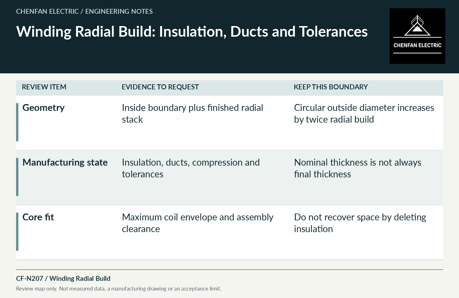
| Review item | Evidence to request | Boundary to preserve |
|---|---|---|
| Geometry | Inside boundary plus finished radial stack | Circular outside diameter increases by twice radial build |
| Manufacturing state | Insulation, ducts, compression and tolerances | Nominal thickness is not always final thickness |
| Core fit | Maximum coil envelope and assembly clearance | Do not recover space by deleting insulation |
References and scope
- Optimizing transformer insulation systemsManufacturer technical page · Interaction of solid insulation, spacers, flow and mechanical support.
- IEC 60076-2:2011 — Temperature rise for liquid-immersed transformersPublic standard abstract · Temperature-rise requirements, cooling identification and the distinction between test conditions and installed duty.
- IEC 60076-3:2013+AMD1:2018 CSV — Insulation levels and dielectric testsPublic standard abstract · Insulation levels, dielectric testing and external clearances; the article does not reproduce test values or design distances.