

A railway autotransformer system contains equipment with different roles, and those roles should not be collapsed into one transformer specification. The main traction transformer interfaces with the upstream source, while line autotransformers serve their defined function within the traction network. Their ratings, connections, insulation and study inputs follow the approved system architecture, not the shared word transformer.
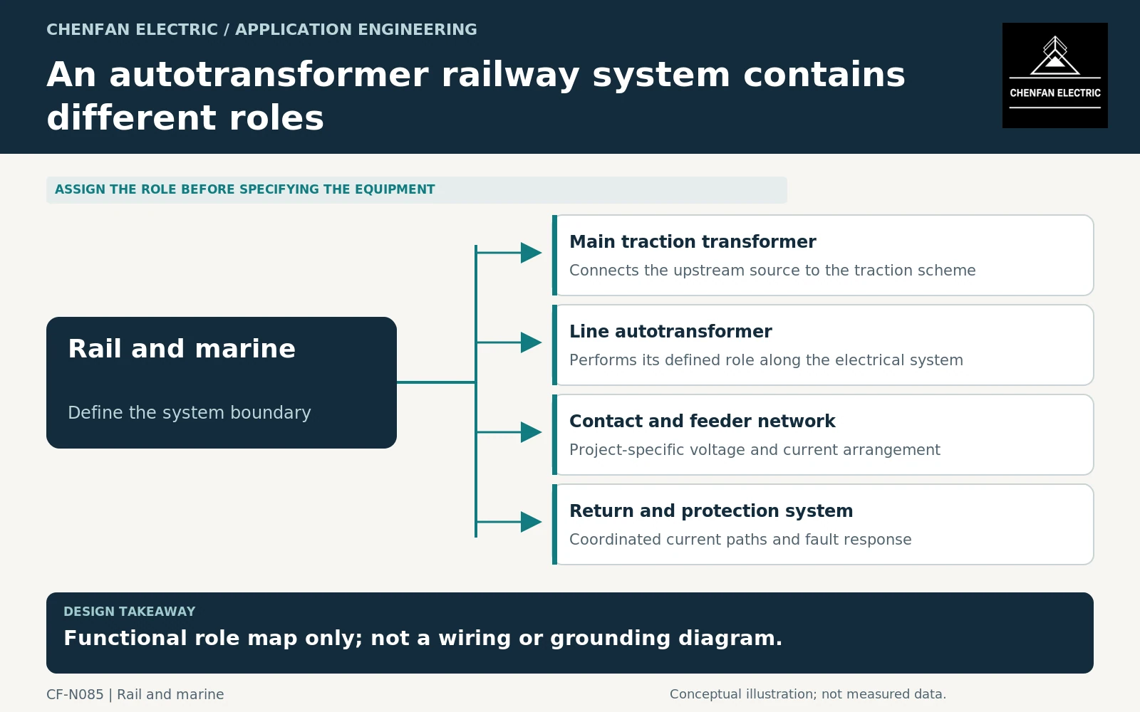
Read the system diagram by function
Identify the upstream source, main traction transformation, contact and feeder network, line autotransformers and return-system interfaces. Use the project’s actual voltage designations and reference points rather than assuming one universal railway voltage scheme.
IEC 62695 addresses transformers for fixed railway installations within its scope. It provides an equipment framework, but it does not replace the system design that assigns each transformer’s role. [1]
A functional diagram can help procurement distinguish equipment categories, but it is not a construction or grounding drawing. Terminal connections, return paths and protection arrangements must come from the approved railway design.
Do not treat an autotransformer as an isolation transformer
An autotransformer arrangement has an electrical connection within its winding system; it should not be described as providing the same galvanic separation as a separately wound isolation arrangement. The implications must be evaluated within the actual traction architecture.
General transformer application guidance addresses transformer connections and operating behavior. Applying it requires the correct equipment representation and reference bases. [2]
The main transformer and line autotransformers can therefore require different models in the network study. A single generic transformer symbol with a nameplate MVA is insufficient to describe their interaction with the traction and return networks.
The enquiry should state the required voltages, currents, connection arrangement and permitted operating cases for each equipment class independently. Do not assume that a main-transformer rating can be divided by the number of line units to obtain their ratings.
Derive duty from network and train scenarios
Train location, demand, regeneration and section configuration affect current distribution. The study should identify relevant normal and unavailable-equipment cases and provide the resulting duty for each transformer role.
A useful equipment schedule separates the source-interface model, line-unit model and system return/protection model. Each should identify parameter owners, reference bases and the operating cases it supports.
The transformer supplier needs the resulting winding duties and insulation requirements, while the system designer owns the complete network behavior. A passed equipment test cannot establish that every section configuration or return-current condition is acceptable.
Dielectric requirements should be coordinated through the applicable transformer insulation framework and project voltage design. IEC 60076-3 has a defined scope and amendment history; it should not be used to infer test levels from a simplified railway voltage label alone. [3]
Keep the purchasing packages coordinated but distinct
Issue separate equipment schedules for the main transformer and line autotransformers, cross-referenced to the same approved system diagram and study revision. Identify differences in physical location, environmental exposure, maintenance access and transport requirements.
Acceptance should reconcile the delivered connection and impedance information with the network model. A later change in sectioning, feeder arrangement or train service can affect duty and should be reviewed against the original assumptions.
The practical outcome is role clarity. The system name explains the architecture, while each transformer’s specification explains its own electrical and physical duty. That prevents procurement from treating unlike equipment as interchangeable merely because all of it participates in an autotransformer railway supply system.
Core procurement checkpoint: Identify the autotransformer role before requesting a core
A railway autotransformer order should be tied to the specific equipment design and connection role in the system. Do not infer the required core arrangement from the route voltage alone, or treat another traction unit’s laminations as interchangeable. The manufacturer should release the geometry and assembly interfaces; system feeding behavior and protection remain outside the core supplier’s manufacturing acceptance.
For the core enquiry: Equipment role and design ID; approved core drawing; grade/thickness; quantities; joint sequence and inspection requirements.