

A Scott-connected transformer enquiry must define the two output duties and the conditions under which they are expected to balance. The connection name alone does not establish winding ratings or balanced loading of the three-phase source. Its ideal relationships are useful, but real unequal loads, power factors and operating states require explicit assessment.
State the function before the connection details
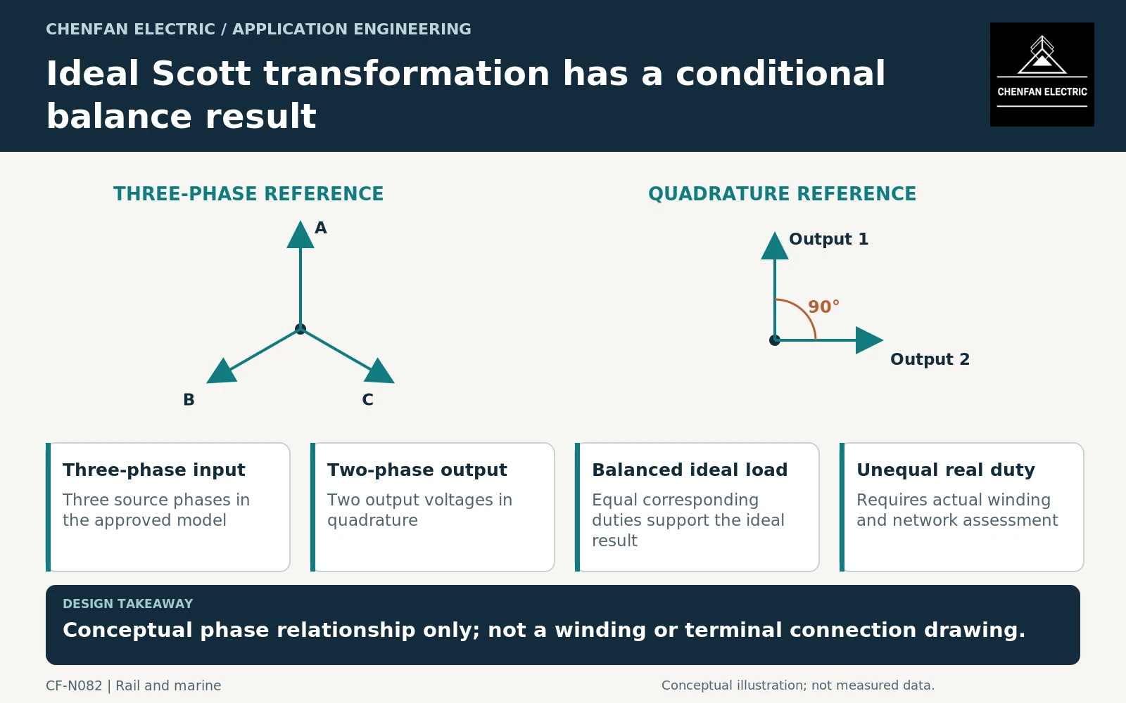
A Scott arrangement is used to relate a three-phase system to a two-phase system with output voltages in quadrature in the ideal representation. It is not simply another conventional three-phase vector-group label.
The familiar balanced-input result depends on corresponding balanced two-phase loading assumptions. Equal output voltage magnitudes alone do not prove that the source currents remain balanced when the loads differ in magnitude or power factor.
Transformer application guidance addresses connection and operating behavior, while fixed-railway transformer requirements may be relevant when the arrangement serves that application. Neither reference removes the need for a project-specific load schedule. [1] [2]
This article describes the specification boundary, not winding turns, terminal wiring or a construction method. Those require the approved design and connection drawings.
Define each output independently
For both output circuits, provide voltage, current, active and reactive power, duration and relevant waveform information. State whether the loads can be unequal, whether one output may be unloaded and whether reverse power is permitted.
A single total MVA can conceal the governing winding condition. The transformer supplier needs the permitted simultaneous combinations, not only the sum of two independent maxima.
An illustrative comparison might pair two equal sinusoidal loads with the same power-factor relationship, then examine one output at full duty while the other is lightly loaded. The point is to expose the change in the balance assumption; no numerical current or unbalance result is claimed here.
The source model should also identify voltage balance and the relevant network impedance. An ideal connection diagram cannot compensate for an unrepresented supply condition.
Separate ideal phasors from acceptance evidence
The conceptual figure shows the intended phase relationship, not measured waveforms or a qualified transformer design. Actual evidence should identify the winding arrangement, ratios, impedance model and tests applicable to the purchased equipment.
| Buyer input | Required clarification |
|---|---|
| Output duties | Independent voltage-current envelopes |
| Simultaneity | Which two-output combinations can occur? |
| Power factor and waveform | Whether ideal balance assumptions remain applicable |
| Unavailable output | Permitted operation with one branch unloaded |
| Source interface | Network conditions and any unbalance requirement |
Do not promise perfect grid balance for every operating state merely because the transformer is Scott connected. The actual load relationship and system model determine the result.
Purchase a bounded operating envelope
The enquiry should attach the approved application diagram, two-output duty matrix and source requirements. Ask the supplier to identify winding limits for asymmetric cases and the model data needed by the system analyst.
Acceptance should distinguish equipment conformity from the connected system’s performance. A transformer test can demonstrate specified characteristics, while the network study establishes the result for the actual load combinations.
Keep later load changes under review. Replacing one connected process or altering a railway section’s duty can change the balance behavior without changing the transformer hardware.
The useful specification says which two-phase loads the arrangement supports and what source behavior is required. “Scott connection required” is only the starting instruction, not the complete technical definition of the equipment or its operating result.
Core procurement checkpoint: Order the specific Scott arrangement, not a generic equivalent
For a Scott-connected system, the transformer designer must establish the complete winding and connection arrangement and the corresponding core geometry. A standard three-phase lamination set is not automatically an equivalent substitute. Identify each required core variant and its assembly interfaces, with any common parts approved explicitly. A drawing-based quotation should not imply approval of the overall Scott connection or load-balance performance.
For the core enquiry: Main/teaser design references as applicable; approved core drawings; quantities; permitted common parts; material and inspection requirements.