

An induction furnace installation can contain transformer functions on different sides of a converter. The upstream transformer may operate at utility frequency while the furnace circuit operates at a different frequency. Specify the transformer’s location, waveform and terminal duty before selecting equipment. The process frequency should not be copied automatically into the rating of an input transformer.
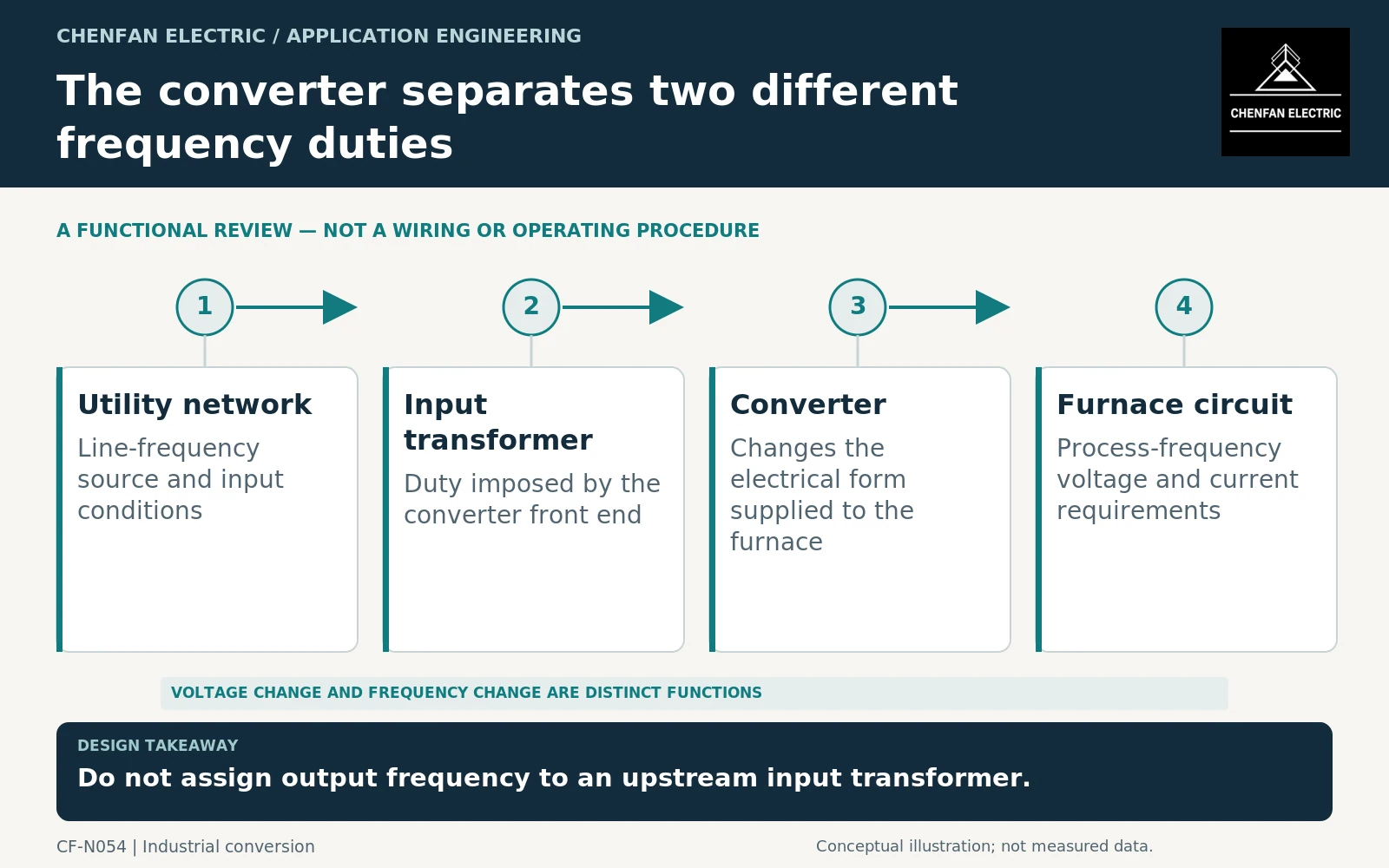
Draw the complete conversion boundary
Show the utility source, input transformation, converter stages and furnace circuit. State voltage, current type and frequency at each boundary. Identify whether the transformer is a separate input assembly, a specialized output component or part of an integrated converter package.
A transformer does not independently change frequency. The converter performs that function, and its location determines the waveform seen by each transformer. Two components serving the same furnace can therefore require very different design information.
IEC 61378-1 and its application guide address industrial converter-transformer interfaces within their defined scopes. They are relevant starting points for the input arrangement, not proof that every high-frequency magnetic component is covered by the same requirements. [1] [2]
Obtain input-side data from the converter supplier
For an upstream transformer, request the converter’s alternating current (AC) input voltage range, continuous and temporary currents, reactive behavior, harmonic spectrum and operating sequence. Include any multiple phase groups or special winding arrangement required by the converter.
Do not calculate the input transformer solely from furnace output power without accounting for the conversion boundary. Losses and auxiliaries intervene, while the current waveform depends on the selected converter topology.
The enquiry should also identify supply-strength assumptions used by the converter supplier. A converter package assessed against one source impedance may require review when connected through a different transformer and network.
Keep output components out of a generic enquiry
A transformer or magnetic component operating in the furnace-side circuit requires its actual waveform, frequency range, insulation duty and cooling conditions. It should not be described simply as a conventional line-frequency transformer with an unusual application name.
| Equipment position | Data that governs the enquiry |
|---|---|
| Utility-side input | Line-frequency voltage, converter input current and spectra |
| Phase-group interface | Required phase relationships and winding duties |
| Converter output | Actual process-frequency waveform and operating range |
| Auxiliary supply | Controls, cooling and service-load sequence |
This distinction also protects the evidence boundary. A core material certificate or a test on one line-frequency assembly does not qualify an unrelated converter-output component.
IEEE C57.110 should not be cited as a universal method for every transformer in the installation. Its published scope excludes rectifier transformers, and specialized converter arrangements require deliberate selection of the specification basis. [3]
Coordinate process cycles and acceptance
Provide the furnace operating sequence, including startup, process changes, idle periods and relevant restart cases. The input current schedule should be derived from the converter’s response to those conditions, not assumed to follow process output instantaneously.
Separate transformer tests from integrated converter-furnace performance. The transformer supplier should confirm the defined winding and thermal duty; the system supplier should own the complete conversion and process interface claim.
The final procurement description should state exactly where the transformer sits and what electrical quantities it receives. That prevents the common ambiguity in “induction furnace transformer,” which can otherwise refer to equipment with fundamentally different frequency, waveform and construction requirements.
Core procurement checkpoint: Identify whether this is a mains-frequency core enquiry
An induction-furnace system can include transformers at different conversion stages. Before specifying CRGO laminations, identify the transformer’s location, frequency and waveform, and obtain the designer’s material selection. Do not imply that a conventional line-frequency core is suitable for every induction-heating converter. Where the duty lies outside the defined manufacturing scope, record the open feasibility question rather than quoting a generic substitute.
For the core enquiry: Converter-stage location; excitation frequency/waveform; designer-selected material; core drawing; feasibility and acceptance requirements.