

The difference between 12-pulse and 24-pulse rectifier transformer arrangements is primarily the converter grouping and phase relationships they support. A higher pulse count can change characteristic harmonic behavior under the intended conditions, but it is not a universal quality grade. The transformer enquiry must define the actual circuit, winding duties and assumptions that make the intended combination work.
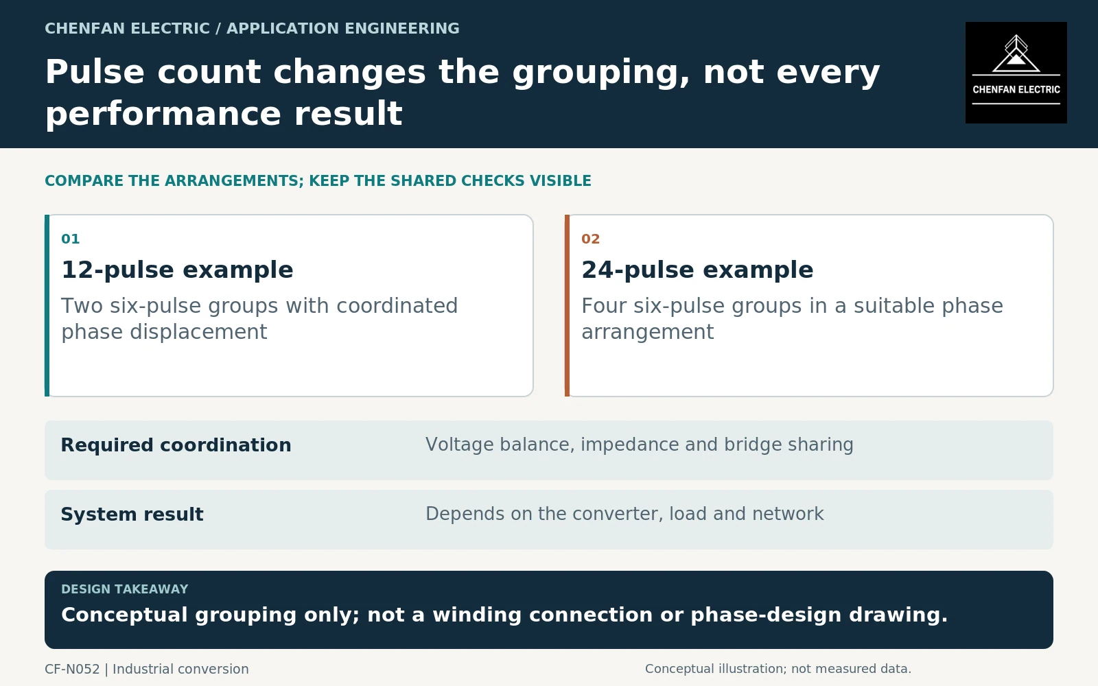
Explain the ideal arrangement without overgeneralizing
In a common idealized arrangement, a 12-pulse system combines two six-pulse bridge groups with a suitable 30-degree phase displacement. A 24-pulse arrangement can use four suitably displaced six-pulse groups. These descriptions explain the concept; they are not a complete winding connection or a claim that every industrial converter uses the same circuit.
The transformer must supply the required phase-related voltages at the specified magnitudes and under load. Converter configuration, current sharing and impedance influence the actual result. IEC 61378-1 and its application guide address industrial converter-transformer arrangements within their scopes. [1] [2]
Do not select the winding connection from a simplified pulse-count diagram alone. The project requires an approved converter schematic and winding schedule.
Identify what changes in the transformer enquiry
More converter groups can introduce additional winding or phase-group interfaces, terminal sets, insulation boundaries and current-sharing requirements. The physical and electrical complexity depends on the chosen arrangement rather than pulse count alone.
Request the phase relationships, winding voltages and currents, impedance requirements, tolerances and permitted asymmetric operating cases. State whether all bridges always operate together or whether partial-group operation is allowed.
| Item | Comparison to make |
|---|---|
| Converter groups | Number, topology and allowed availability states |
| Transformer outputs | Required voltage magnitudes and phase relationships |
| Current sharing | Assumptions and tolerances under load |
| Regulation | How the direct current (DC) range is achieved across operating states |
| Terminals | Physical connections, cooling and access requirements |
A 24-pulse label does not tell the supplier whether the arrangement uses one transformer, several transformers or additional phase-shifting elements. That architecture must be specified.
Treat harmonic cancellation as conditional
Ideal harmonic cancellation depends on the intended phase relationships and sufficiently compatible group operation. Unequal loading, voltage imbalance, impedance differences and the surrounding network can change the residual harmonics.
Do not promise that doubling pulse count halves total harmonic distortion. A single percentage cannot be derived from the label without the converter, load and network conditions. Distinguish characteristic behavior of an ideal circuit from measured or guaranteed performance of the installed system.
ABB’s harmonic material provides the broader nonlinear-load context. IEEE C57.110 is not the default design basis for these rectifier transformers because its scope explicitly excludes that equipment class. [3] [4]
Compare complete system guarantees
Ask each offer to state the operating points at which input-current and output-performance guarantees apply. Include partial load, relevant group outages and the actual supply-voltage conditions. A favorable full-load result with all groups available does not establish every degraded mode.
The transformer evidence should cover its specified winding, impedance and thermal duties. The converter-system evidence should cover the resulting combined performance. Neither should be substituted for the other.
The useful comparison is therefore not “24 pulse is better.” It is whether the additional grouping delivers a required system outcome under the project’s actual conditions, and what transformer complexity, controls and maintenance interfaces are needed to obtain that outcome.
Core procurement checkpoint: Do not attribute phase displacement to the lamination pattern
The phase relationships needed by a multi-pulse rectifier are established by the complete transformer connection and winding design. A step-lap arrangement is not a substitute for that electrical design. For the core order, use the specific limb, window and assembly geometry approved for the chosen 12-pulse or 24-pulse arrangement, and identify non-interchangeable variants explicitly.
For the core enquiry: Approved converter-transformer core drawings; variant quantities; window and limb dimensions; joint pattern; assembly and inspection instructions.