

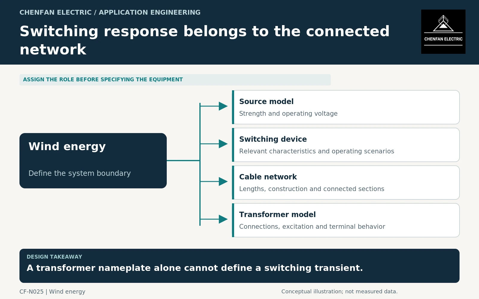
A transformer switching study in a wind farm needs the connected cable network, switching-device characteristics and transformer model—not only transformer MVA and impedance. Energization and other switching events can involve different timescales and mechanisms. Define the event being studied before selecting model detail or accepting a generic surge-protection statement.
Separate energization from other switching questions
Transformer energization can involve nonlinear excitation, residual flux and the source response. Other events may involve fast terminal transients, cable behavior or switching-device characteristics. A model adequate for one question may not resolve another.
CIGRE’s transformer-energization study-guide summary identifies voltage dips and temporary overvoltages as system-level consequences requiring appropriate analysis. It does not provide a universal outcome for every wind-farm cable arrangement. [1]
State the switching location and initial network configuration. Energizing a transformer through a short connection is not the same case as energizing it through a long collector cable with other equipment connected.
Collect data by physical component
The network model should use the actual cable sections, including relevant construction data, lengths and termination arrangement. Identify which sections are energized together and which remain disconnected in each case.
Obtain switching-device data appropriate to the phenomena under review. Do not invent breaker characteristics to make a simulation run, and do not assume that a generic ideal switch represents every relevant switching effect.
| Component | Data package to request |
|---|---|
| Source | Voltage, impedance and credible operating configurations |
| Cable network | Section lengths, parameters and connection states |
| Transformer | Winding connections, excitation and suitable terminal model |
| Switching device | Relevant characteristics and operating constraints |
| Connected equipment | Compensation, converters and other participating branches |
The required detail should follow the study objective. Avoid burdening a load-flow model with unsupported high-frequency parameters, or presenting a simplified steady-state model as a transient validation.
Test a defensible range of initial conditions
The case register should identify switching instants, transformer initial-state assumptions and connected cable configurations where they are relevant. A single favorable event does not establish the envelope of response.
PSCAD documentation describing energization-case sweeps illustrates a way to explore varying closing conditions. It is a modeling workflow reference, not evidence that a particular wind farm has been simulated or passed a study. [2]
Keep assumptions traceable. Where parameters are estimated, identify their source and assess whether uncertainty changes the conclusion. Numerical precision in a plot cannot compensate for an unvalidated transformer excitation curve or an incorrect network configuration.
Link conclusions to equipment and operating decisions
The study should report which cases govern, what acceptance basis was used and which design or operating restrictions follow. Any mitigation must be selected by the responsible system engineers and coordinated with equipment ratings and protection.
Transformer dielectric requirements have their own test and insulation framework. A switching study does not replace the specified transformer tests, and a passed factory dielectric test does not automatically demonstrate every site transient condition. [3]
For procurement, request an agreed model-input list, study responsibility matrix and a schedule for closing missing parameters. That keeps a late cable or breaker change from silently invalidating the assumptions used to approve the transformer interface. The deliverable is a bounded system conclusion, not a generic statement that wind-farm transformers are “switching-proof.”
Core procurement checkpoint: Separate switching-study inputs from production acceptance
Cable switching studies may require an equipment model that represents excitation and saturation appropriately for the study. Agree who provides and validates those characteristics. A lamination drawing or single core-loss result is not a complete transient model. Core manufacturing records should identify the supplied geometry and test configuration without claiming that they establish safe switching for the wind-farm cable network.
For the core enquiry: Model-data owner; approved core geometry; excitation-test scope if requested; manufacturing revision; study assumptions retained by the project.