

A transformer with two low-voltage (LV) windings can connect separate photovoltaic (PV) inverter blocks without placing both groups on the same low-voltage bus. That separation can be useful, but it does not create two fully independent transformers. The windings share a magnetic system and usually a common physical assembly. Ratings, impedances, fault effects and maintenance boundaries must be evaluated as a multiwinding arrangement.
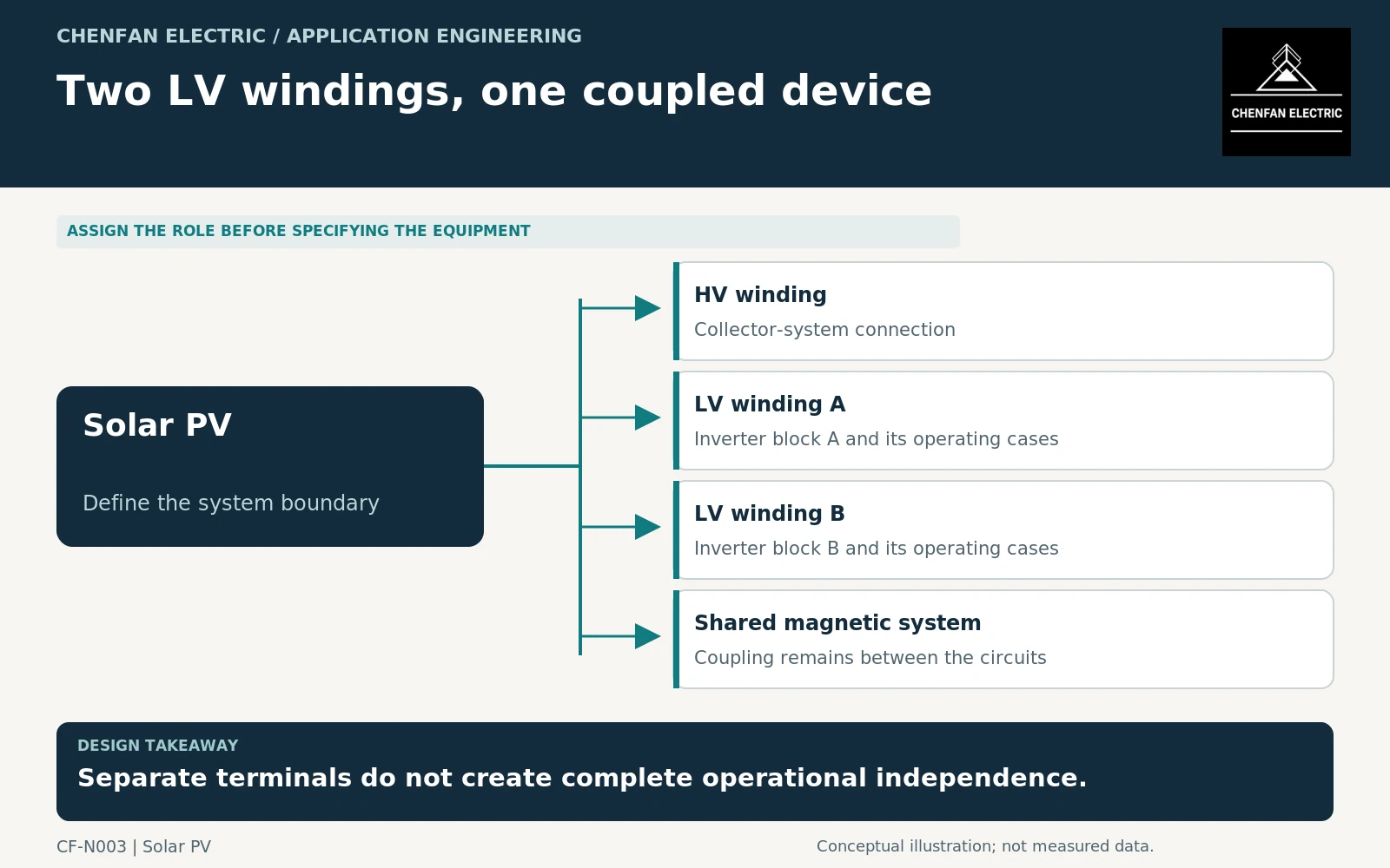
Define what the separation is intended to achieve
Begin with the project objective: reduced bus current, a particular converter topology, separate inverter groups, or a desired maintenance arrangement. These objectives are not interchangeable. A separate LV terminal set may simplify one interface while leaving common transformer outages unchanged.
Compare three explicit alternatives: one common LV bus, two LV windings on one transformer, and two separate transformers. Mark which components remain shared in each arrangement, including the high-voltage connection, cooling equipment, protection functions and enclosure. General transformer application guidance covers connections and operating considerations, but the required availability outcome must come from the project. [1]
Avoid describing the two-winding branches as “fully isolated” without defining whether that refers to galvanic separation, protection zones or continuity of service. Those are different claims, requiring different evidence.
Request a rating schedule for every winding
State each winding’s voltage, current and operating duty, including the permitted simultaneous combination. The sum of two independently quoted maximum outputs may exceed an allowed common-transformer condition. Conversely, a shared total rating alone may conceal an individual LV current limit.
Consider unequal operation. One inverter group may export at full output while the other is unavailable, importing auxiliary power or providing reactive support. The resulting duty cannot be represented adequately by assuming equal loading at all times.
| Condition | Question the supplier must resolve |
|---|---|
| Both groups exporting | Which simultaneous winding ratings apply? |
| Only group A operating | Is the proposed asymmetric duty covered? |
| Group B disconnected | Which terminals and components remain energized? |
| One group providing reactive power | How is each winding current assessed? |
Include control restrictions that enforce these limits. A rating depending on a plant controller should identify the limit and the consequence of controller unavailability.
Specify impedance by winding pair
A single percentage-impedance figure is not a complete description of a three-winding transformer. The study model needs the relevant pairwise impedances, their reference bases, tap conditions and tolerances. Values on different power bases must not be compared as though they were directly equivalent.
Provide the connection arrangement and neutral treatment for every winding. Phase relationships and zero-sequence behavior affect converter compatibility and fault studies. Where converter-specific phase shifts or coupling requirements apply, converter-transformer guidance may become relevant, but merely connecting an inverter does not establish that every special converter provision is required. [2]
Do not replace a fault study with the intuition that separate winding terminals prevent interaction. Magnetic coupling, network connections and protection operation can still make an event on one branch affect the other.
Define evidence at the assembly boundary
The deliverable should combine a winding schedule, approved connection diagram, pairwise-impedance model, simultaneous operating matrix and a protection-boundary review. Identify the conditions under which one inverter group can be maintained while another remains in service; this requires an engineered isolation arrangement, not a slogan in a purchase specification.
Also distinguish component evidence from assembly evidence. A core dimensional check or material certificate does not demonstrate the complete transformer’s winding insulation, impedance or fault performance. IEC 60076-1 establishes a general transformer framework, while project-specific features require their own agreed treatment. [3]
Choose the arrangement that resolves the intended electrical interface with documented operating limits. Do not pay for extra terminals while leaving the fundamental separation objective undefined.
Core procurement checkpoint: Freeze the multi-winding mechanical envelope
Two low-voltage windings require an agreed coil arrangement and insulation space, not merely a common aggregate MVA label. Before ordering laminations or a pre-stacked core, the transformer manufacturer should freeze the window, limb steps and assembly clearances. The steel supplier’s processing scope should not be mistaken for approval of winding connections, load sharing or the unit’s multi-winding thermal design.
For the core enquiry: Approved multi-winding outline; limb steps and stack dimensions; window clearances; joint sequence; delivery form and drawing revision.