

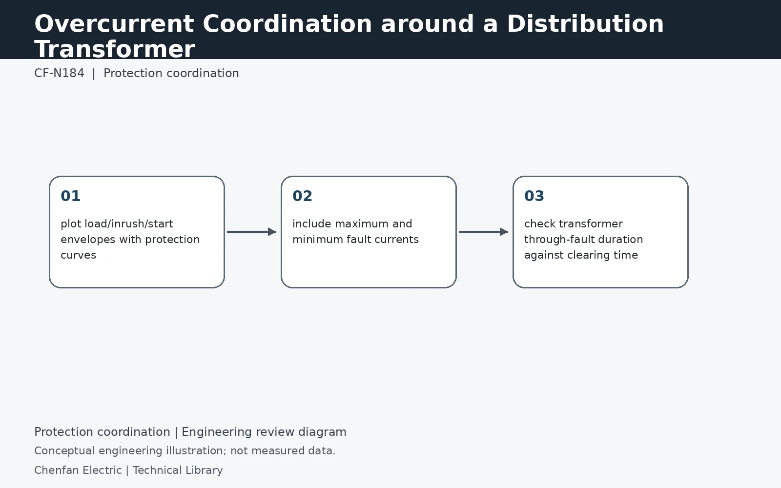
Overcurrent coordination around a distribution transformer must protect the transformer without tripping on legitimate load pickup, motor starting or short-duration inrush. The same curves must also coordinate with downstream protective devices and remain below the transformer through-fault capability where applicable. Use maximum/minimum fault cases and realistic load transients rather than one static current multiple.
Compare curves on one current reference
Primary and secondary currents differ by the transformer ratio, so device curves and transformer limits must be referred to a common side before comparing them. As an illustration, 1 MVA at 11 kV corresponds to about 52.5 A three-phase rated current, while at 400 V it is about 1,443 A. These are the same apparent-power duty on different sides. Include tap and ratio assumptions so an apparent coordination margin is not simply a scaling error.
Separate legitimate transients from fault duty
Motor starting, cold-load pickup and transformer energization have different current-time behavior. Represent the events relevant to the installation instead of allowing one broad inrush envelope to mask every other constraint. The protection must avoid unwanted operation for permitted service while still clearing faults within the equipment's capability. Through-fault withstand and overload thermal capability are not interchangeable curves, so use the correct manufacturer or applicable guide data for each comparison.
Check weak-source clearing as well as strong-source duty
Maximum fault current may govern interrupting capacity, but minimum remote-fault current can govern pickup and clearing time. Include alternate sources and the conductor impedance to the downstream fault. Where the primary device backs up secondary protection, evaluate the actual current it sees and the total clearing time, including breaker or fuse behavior. The issued coordination study should identify any nonselective region or unresolved constraint instead of presenting a single nominal-current multiple as a complete solution.
Technical reference framework
[1] IEEE C37.91-2021 — Protecting power transformers.
[2] IEC 60076-1:2011 — Power transformers, General.
[3] IEEE C57.109-2018 — Liquid-immersed transformer through-fault-current duration.