

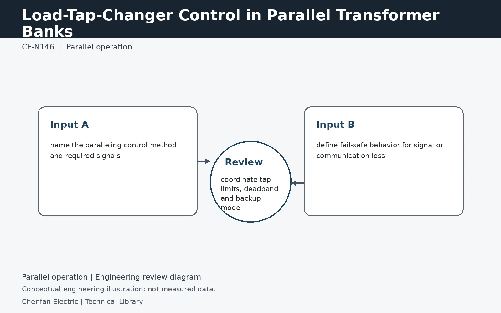
Parallel OLTC control is a control-system problem layered on top of electrical compatibility. Master/follower, circulating-current and other methods make different assumptions about tap position feedback, voltage sensing, reactive current and communications. The specification should define the permitted control philosophy, loss-of-communication behavior, tap limits and backup mode rather than merely requiring that the units “operate in parallel.”
The controller cannot repair incompatible transformers
Parallel control presupposes acceptable phasing, ratios and impedance-based loading. A master/follower arrangement coordinates commands or positions, but identical indicated positions may not give identical ratios on different tap schedules. Circulating-current methods use electrical feedback and need correctly related current measurements. Choose the philosophy against the actual transformer data and CT/VT interfaces. A control-system claim of “parallel capable” is not evidence that the proposed bank is electrically compatible across its intended tap range.
Define a credible response to missing information
Loss of communications, invalid tap indication or a failed VT should not leave the operating mode undefined. State the required alarm, blocking, fallback or operator intervention for each failure, subject to the approved station philosophy. Check that a fallback local controller cannot unknowingly drive one unit away from the other. The supplier should disclose which decisions depend on transmitted data and which remain local, so that the failure review tests the real architecture.
Test transitions between single and parallel service
Acceptance testing should include bank entry and exit, a transformer reaching its tap limit, unavailable voltage feedback and recovery after communication loss. Confirm the active controller mode, ratio mapping and command ownership in each state. These are functional test objectives, not instructions for operating live switchgear. Preserve event logs and expected results so later firmware or control-setting changes can be checked against the same requirements rather than only against a normal steady-state demonstration.
Technical reference framework
[1] IEC 60076-8:1997 — Application guide.
[2] Schneider Electric — Substation including generators and parallel operation of transformers.
[3] IEC 60214-1:2014 — Tap-changers, Performance requirements and test methods.
[4] IEEE C57.131-2024 — Tap-changers, Performance requirements and test methods.