

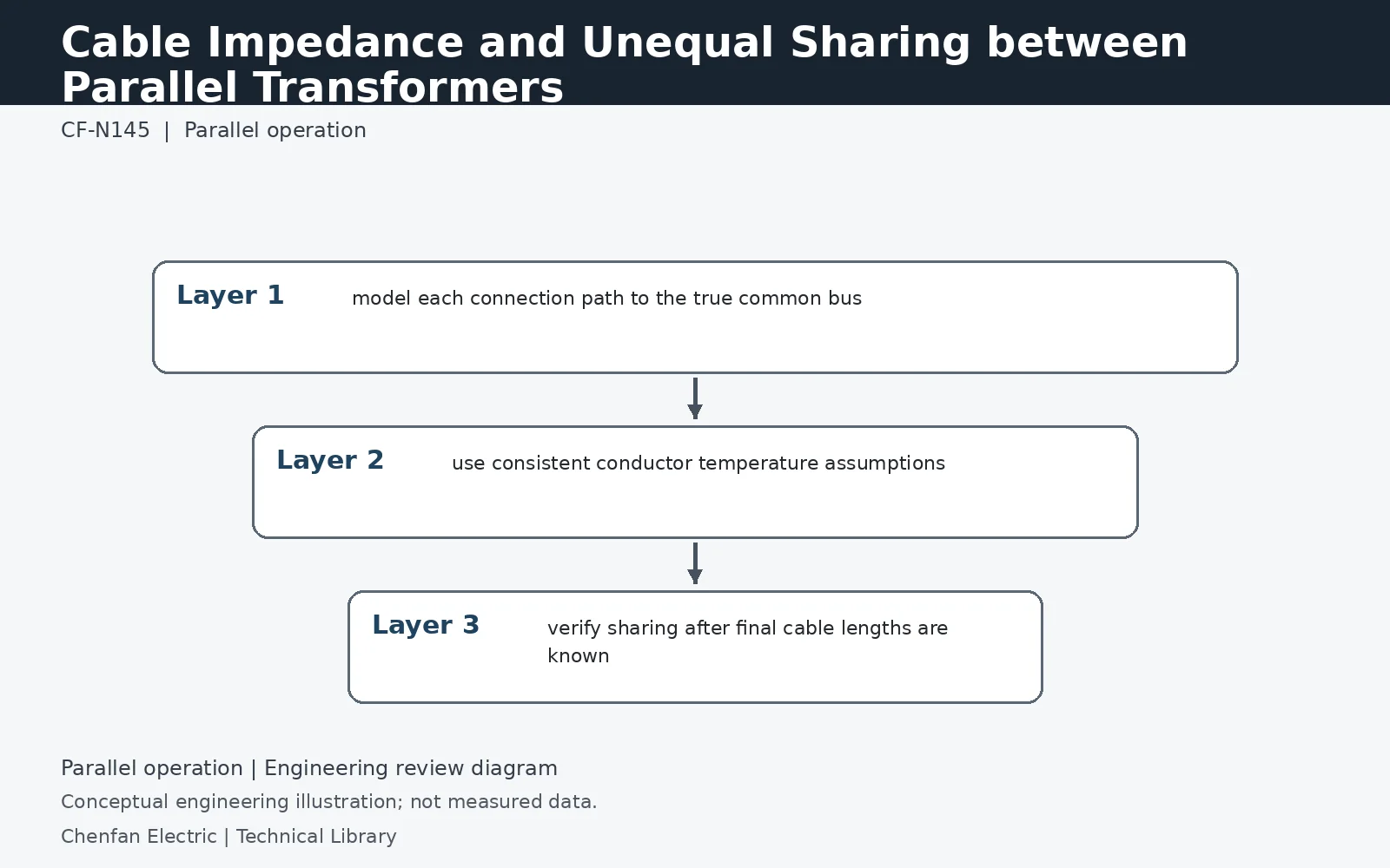
Cable or busduct impedance between each transformer and the common bus becomes part of the sharing impedance. Different lengths, conductor sizes, temperatures or routing can make otherwise identical transformers share unequally. The parallel model should start at each transformer terminal and include the full connection to the common point; measured or design cable data should use consistent temperature and frequency assumptions.
Nameplate equality ends at the transformer terminals
Consider identical transformer impedances of 0.060 per unit. If their connection paths add 0.002 and 0.010 per unit at the same angle, the total branch impedances become 0.062 and 0.070. With equal source voltages, the shorter-impedance branch carries 0.070/0.132 = 53.0% of the load rather than 50%. This scalar example is deliberately simplified; actual cable resistance and reactance must be combined as complex quantities with the transformer impedance.
Conductor temperature changes the resistance component
The two connection paths may not operate at the same temperature, particularly when their loading, enclosure or cooling differs. Use resistance values appropriate to the study condition rather than mixing a cold-test value with a hot operating value. Parallel conductors also require correct length, arrangement and sharing assumptions; counting the number of cables is insufficient. Record busduct joints and other significant series elements so that the model corresponds to the installed current path, not only to the cable catalogue.
Treat a cable replacement as an electrical change
Replacing one connection with a larger conductor can improve its own ampacity while shifting more bank load into that transformer. A route extension can have the opposite effect. The bank study should therefore be revisited when length, size, route or termination arrangement changes materially. Compare measured load-sharing data at a known operating state with the model, but do not infer the cause of a mismatch from one clamp-meter reading without voltage, power-factor and temperature context.
Technical reference framework
[1] IEC 60076-8:1997 — Application guide.
[2] Schneider Electric — Substation including generators and parallel operation of transformers.