

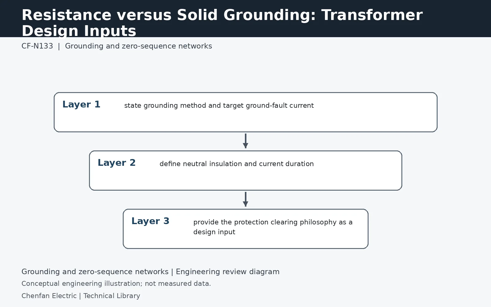
Solid and resistance grounding impose different zero-sequence currents and protection objectives. The transformer designer needs the intended grounding method, resistor value or target current, system voltage, fault duration, neutral insulation and connection arrangement. The specification should not ask the transformer manufacturer to infer the grounding philosophy from a one-line diagram alone.
Write the sequence circuit before selecting a method
For a simplified single-line-to-ground fault, the positive-, negative- and zero-sequence networks are connected in series. A neutral impedance Zn appears as 3Zn in the zero-sequence circuit because the neutral carries 3I0. This is why adding a grounding resistor changes more than a drawing symbol. Solid grounding removes the intentional resistor, but transformer, source and conductor impedances still limit current. Neither method defines a fault-current value independently of the network to which it is applied.
Protection objectives determine the required data
Record whether the installation requires rapid fault isolation, a defined first-fault operating regime, or selective detection across several feeders. These objectives influence the grounding design, but they do not authorize a universal resistor current or relay pickup. System charging current, fault resistance and CT sensitivity must be assessed by the responsible engineer. A proposal based only on transformer kVA cannot resolve these questions, especially when future cables or parallel sources will change the network.
Assess neutral voltage as well as neutral current
Limiting ground-fault current does not automatically reduce every insulation duty. Neutral displacement and the duration of elevated phase-to-earth voltage can become decisive. The transformer neutral, grounding assembly and associated arresters must be evaluated against the same operating states. Ask for a specification that identifies nominal and maximum system voltage, expected temporary overvoltage, fault-clearing assumptions and permitted grounding configurations. Compare competing offers on those common conditions rather than accepting unlike grounding philosophies as equivalent equipment.
Technical reference framework
[1] IEC 60076-8:1997 — Application guide.
[2] IEC 60076-1:2011 — Power transformers, General.
[3] Post Glover NG112-06 — Neutral grounding resistors: Technical information.
[4] Post Glover GT210-10 — Neutral grounding resistors with transformer.