

Amorphous and cold-rolled grain-oriented electrical-steel cores should be compared as compatible designs, not as interchangeable material labels on an unchanged drawing. Their magnetic data, usable operating range, material form and assembly requirements differ. A favorable loss figure for one material does not by itself prove that an existing winding and core arrangement can accept it without redesign.
Compare the material at a defined condition
Cold-rolled grain-oriented electrical steel, often abbreviated CRGO, and amorphous metal are distinct material systems. A manufacturer’s amorphous transformer-alloy data describe a specific alloy, processing state and core product rather than a universal property for every amorphous core. [1]
Compare loss and excitation data at matching flux density, frequency, waveform, temperature and test-object definition. Material specimens and finished cores must remain separate. A quoted percentage saving against an unspecified steel grade is not a usable design comparison.
The allowable operating flux should come from the selected material and design evidence. Saturation induction is not automatically the recommended working flux density, and one published saturation value is not a complete temperature or waveform envelope.
Recalculate area, turns and winding fit together
For sinusoidal induced voltage, the familiar voltage-per-turn relationship links frequency, net magnetic area and peak flux density. [2] A change in permissible working flux can therefore require a different net area, turn count or both.
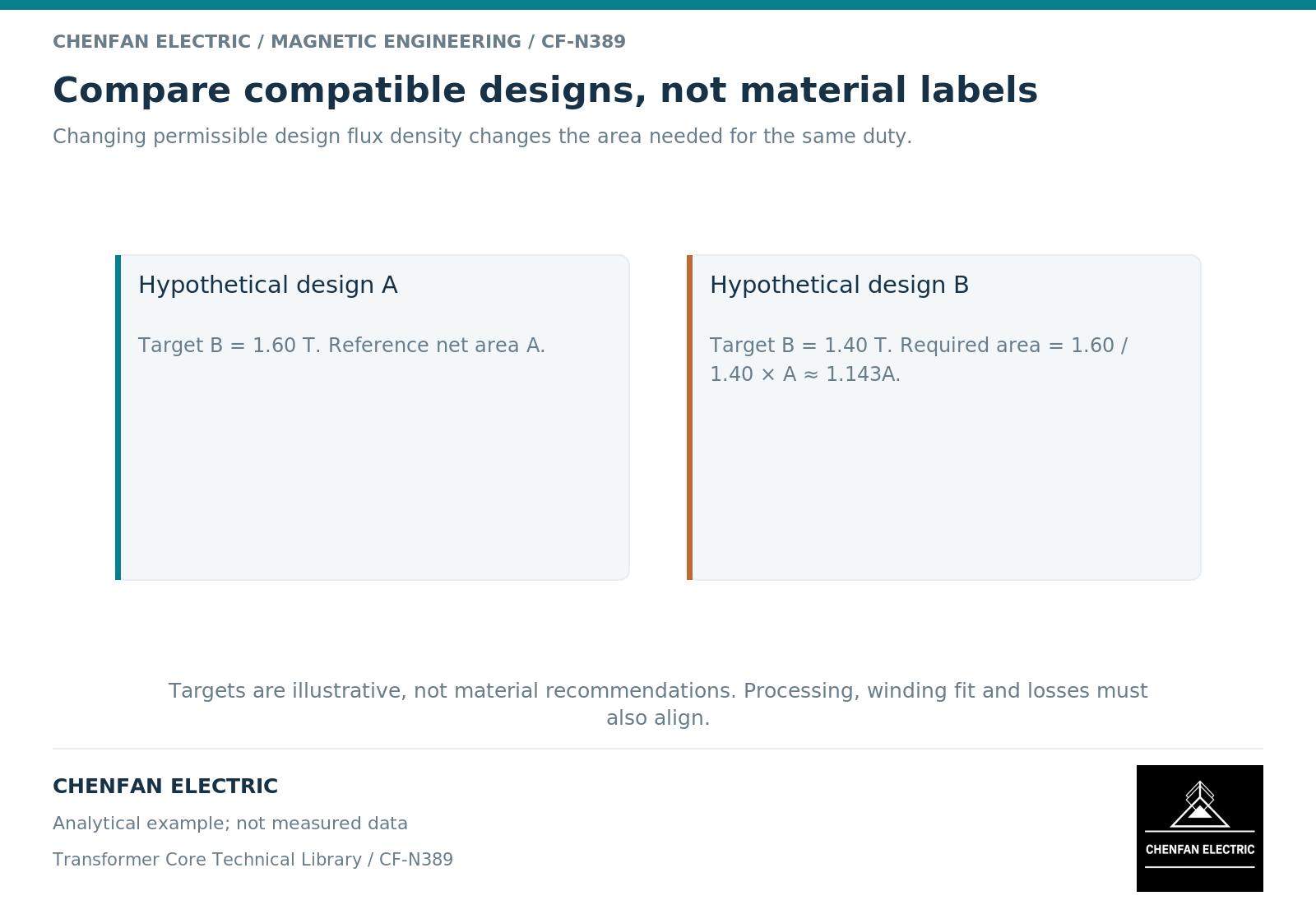
As an illustrative dependency, reducing a chosen design flux density from 1.60 T to 1.40 T while retaining frequency and induced volts per turn requires net area to increase by 1.60/1.40, about 14.3%. These are hypothetical design targets, not recommended values for either material.
Increasing area can change the core outline and winding mean turn length. Increasing turns changes conductor length and window occupancy. Either route must be checked against insulation, cooling and the existing winding interface.
Treat mechanical compatibility as a release condition
| Interface | Comparison requirement |
|---|---|
| Material form and core construction | Actual available geometry and assembly method |
| Net magnetic area | Definition consistent with the supplied structure |
| Winding installation | Opening, support and handling compatibility |
| Clamping and restraint | Approved arrangement for the selected core system |
| Loss evidence | Material or finished-core scope clearly identified |
| Complete-transformer performance | Recalculated and verified for the integrated design |
A supplier’s statement that a core uses familiar assembly techniques does not establish compatibility with every existing design. The specific opening, support and restraint details still need to be checked.
Likewise, processing and handling requirements should come from the selected material and core supplier. Do not assume that a manufacturing operation acceptable for one material is harmless for the other.
Compare complete outcomes without borrowing claims
A meaningful evaluation considers no-load loss, load-related consequences of winding changes, excitation, temperature, noise where specified, dimensions, mass and commercial constraints. It also states which quantities are calculated, guaranteed or actually tested.
The result may favor different designs under different duty and cost assumptions. It should not be presented as a universal percentage improvement or a same-drawing substitution promise.
Chenfan Electric’s educational comparison does not assert unverified amorphous-core production capability. For a proposed substitution, the useful next document is a coupled magnetic and mechanical redesign review, followed by evidence for the actual supplied core and transformer—not a material-name change on the original bill of materials.
References
[1] Metglas. Distribution Transformer Electrical Steel.
[2] Lloyd Dixon / Texas Instruments. Magnetics Design 1 – Introduction and Basic Magnetics.