

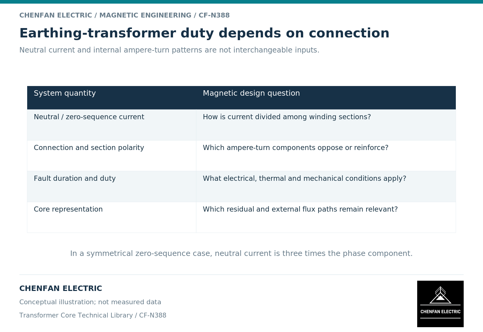
A grounding transformer core must be evaluated with its winding connection and earth-fault duty. Neutral current is not automatically a direct measure of main-core flux. In a zigzag arrangement, winding sections are connected so that relevant zero-sequence ampere-turns can oppose on a limb; the resulting impedance and local fields depend on the actual arrangement, not a conventional transformer rating shortcut.
Identify the electrical connection first
Grounding transformers provide a neutral point for systems that require one. Manufacturer descriptions identify zigzag and star-with-delta arrangements as possible implementations and distinguish this function from an auxiliary load that may also be supplied. [1]
The connection determines how phase and zero-sequence currents flow. For equal zero-sequence phase currents, neutral current is three times an individual phase’s zero-sequence current. This is a current relationship, not a statement that each core limb carries three times the normal flux.
A core review therefore needs the winding-section turns, polarities and placement. A single total-turns figure can hide the opposing magnetomotive forces that define the intended behavior.
Distinguish main magnetic flux from fault-related fields
The applied voltage and winding connection establish the main excitation. During an earth fault, additional current distributions create leakage fields and forces. Magnetic equivalent-circuit approaches emphasize the need to preserve winding-to-core mapping and return paths when representing multi-limb behavior. [2]
In an idealized zigzag limb with equal, oppositely acting sections carrying the relevant equal currents, their zero-sequence ampere-turns cancel. Real leakage impedance remains because the spatially separated windings do not cancel their fields everywhere. Unequal sections or a different connection require a different analysis.
This is why a neutral-current requirement cannot be converted directly into a core flux density by ignoring the winding topology. It is also why a low main-flux increment does not mean the fault imposes negligible winding or structural duty.
Keep continuous and short-time requirements separate
| Duty element | Design information required |
|---|---|
| Continuous energization | Voltage, frequency, connection and excitation limits |
| Neutral earth-fault current | Magnitude, duration and associated system conditions |
| Zero-sequence impedance | Definition, tolerance and test basis |
| Auxiliary load, where present | Continuous loading and interaction with other duties |
| Fault-related fields and forces | Winding-section geometry and current distribution |
| Thermal recovery | Repetition and initial thermal condition |
A short-time current duty is not interchangeable with a continuous load rating. The permitted duration and repetition must remain visible rather than being compressed into one apparently comparable apparent-power value.
The system’s protection and grounding impedance are also part of the application. They cannot be approved from the core drawing alone.
Release a topology-specific core requirement
The core manufacturer needs the controlled magnetic structure and the operating envelope relevant to that structure. The transformer designer must retain the winding connection, zero-sequence performance, dielectric design and short-time thermal and mechanical verification.
A material or geometry substitution should be reviewed against those duties, particularly where return paths or local field exposure change. Familiarity with standard distribution-transformer cores does not establish qualification for a grounding-transformer assembly.
The useful handover states how the winding connection uses the core under normal and earth-fault conditions. That avoids both overestimating main-core flux from neutral current alone and underestimating the serious current-related duty carried by the complete active part.
References
[1] Hitachi Energy. Earthing transformers.
[2] Manitoba Hydro International / PSCAD. The UMEC Approach.