

A shunt reactor core should be specified from the required reactive-power duty, voltage range and frequency before selecting its geometry or material. Its purpose differs from a power-transfer transformer: it absorbs reactive power through an inductive current. The magnetic design must support that current and the associated energy, loss and mechanical duty over the stated operating envelope.
Translate the system requirement into a phase duty
A manufacturer description identifies shunt reactors as reactive-power absorbers used with transmission lines and cable systems, with connection directly to a line or to a transformer tertiary. [1] Those applications do not define one universal core construction or operating range.
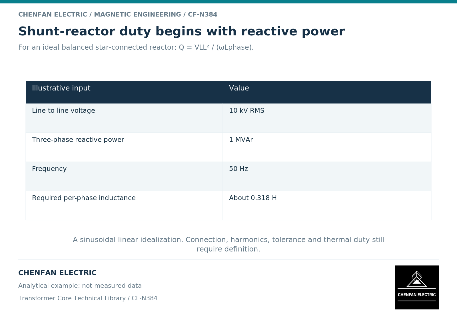
For a balanced ideal linear three-phase reactor, total reactive power is Q = 3Vph²/(ωLph), where Vph is phase root-mean-square voltage, Lph is the corresponding phase inductance and ω = 2πf. The connection determines how phase voltage relates to line voltage.
For an illustrative star-connected reactor at 10 kV line voltage, 50 Hz and 1 Mvar total duty, the ideal phase inductance is approximately 0.318 H. This follows from Lph = Vline²/(ωQ). It is a circuit calculation, not a released reactor design, and excludes nonlinear and loss effects.
State how inductance changes over the envelope
A nominal inductance at one operating point does not fully describe a magnetic reactor. The designer needs the voltage and frequency range, the intended linearity or regulation behavior, and any variable-reactance operating states.
Gapped magnetic structures can support energy-storage duties while controlling the relation between current and flux. Fundamental inductor guidance explains why the gap and its surrounding field matter. [2] The manufacturer’s published gapped-core shunt-reactor description is one implemented approach, not proof that every reactor should use the same construction. [1]
Switching and abnormal system conditions may require additional study. They should be specified as identified cases rather than folded into an unexplained “safety margin.”
Include local fields and mechanical duty
| Input | Magnetic-design consequence |
|---|---|
| Rated and operating voltage | Establishes excitation and reactive-current range |
| Frequency and spectrum | Changes impedance, excursion and losses |
| Fixed or variable duty | Defines required characteristic and operating states |
| Gap and winding layout | Influences fringing and structural exposure |
| Cooling system | Constrains permissible heat generation |
| Required mechanical and acoustic behavior | Requires force and structural assessment |
A gap can create localized fringing near windings and supports. Therefore, core material loss alone is not the reactor’s total loss, and a low material-loss figure cannot establish the temperature of the assembled device.
The complete design must also preserve insulation and mechanical functions. A magnetic layout that meets nominal inductance may still require revision when these interfaces are evaluated.
Make the procurement boundary explicit
For a core-only enquiry, identify the released magnetic structure, material state, gap arrangement and dimensional requirements, plus any contracted evidence at the core assembly level. For a complete reactor enquiry, the manufacturer must address the electrical, thermal, dielectric and mechanical system.
Do not infer complete-reactor capability from a supplier’s transformer-core experience or from an educational article about shunt reactors. The product scope and qualification evidence must be established separately.
A useful specification links the system’s reactive-power requirement to a defined phase duty and then to a controlled magnetic and assembly design. Starting with a familiar core shape reverses that logic and can leave the most important operating questions unresolved.
References
[1] Hitachi Energy. Shunt reactors.
[2] Lloyd Dixon / Texas Instruments. Magnetics Design 5 – Inductor and Flyback Transformer Design.