

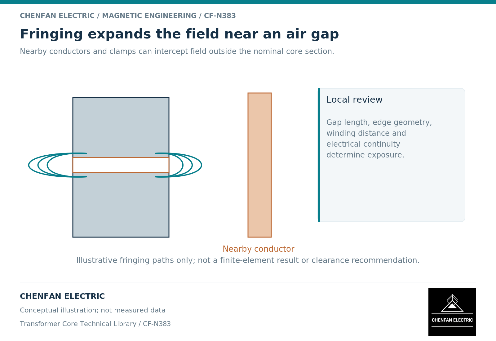
Air-gap fringing is the spreading of magnetic field around a gap rather than confinement to the core’s nominal cross-section. It changes the local field seen by nearby conductors and can add heating that a one-dimensional reluctance calculation does not resolve. The relevant distance is a design outcome, not a universal clearance copied between reactor sizes.
Understand the limitation of the simple gap equation
The expression Rg ≈ g/(μ₀A) assumes a uniform field over area A. Fringing effectively changes the field distribution and can change the relationship between gap length and inductance. Inductor design guidance treats this explicitly rather than assuming the core cross-section fully describes the gap field. [1]
A correction factor fitted to one gap shape is not automatically valid for another. Gap aspect ratio, nearby return material and the winding position can all matter. At multiple gaps, interactions between neighboring fringe regions may also become relevant.
The simple equation remains useful as a baseline. A more detailed model should explain why its result differs, not merely replace the analytical estimate with an unexplained number.
Examine conductors by orientation and spectrum
Changing flux through a conductive region can induce current circulation. The resulting loss depends on field orientation, frequency, conductor geometry and electrical properties. Field-model documentation treats conductivity and induced-current distribution separately from magnetic reluctance. [2]
A conductor close to a gap may experience a field component that differs from the field along the core limb. Therefore, a winding-loss estimate based only on uniform longitudinal field can miss local exposure.
Root-mean-square current does not fully specify this duty. The ripple spectrum and phase relationships determine the time-varying source, while direct-current bias sets a different part of the operating condition. A steady bias and an alternating fringe field should not be assigned the same loss mechanism.
Use a local model within a complete assembly context
| Required information | Reason |
|---|---|
| Gap dimensions and positions | Defines the source region and edge geometry |
| Core constitutive response | Determines local field redistribution |
| Winding and hardware locations | Identifies exposed conductive volumes |
| Current waveform and bias | Defines magnetic excursion and frequency content |
| Electrical continuity | Determines available induced-current paths |
| Cooling interfaces | Connects local loss to temperature |
A local three-dimensional submodel can be useful when the gap region controls the decision. Its boundary conditions must be consistent with the larger magnetic circuit. Otherwise an artificially imposed field may overstate or suppress the relevant fringing.
Check mesh sensitivity near edges, but avoid treating a point singularity as a directly measurable hot spot. Use a reporting metric with a physical location and averaging definition.
Evaluate mitigations without prescribing construction details
Changing gap placement, conductor placement, segmentation or surrounding structures can alter fringing exposure. Each option also affects inductance, mechanical support, insulation or manufacturability. No one change is automatically acceptable across all reactor designs.
Compare candidates under the same duty and report both local loss and heat removal. A lower total electromagnetic loss does not alone establish a lower maximum conductor temperature.
The final review should identify the affected region, model assumptions and supporting verification. It should not produce a generic spacing rule or authorize modification of an existing assembly. Fringing is a localized field problem embedded in a complete design, and its treatment must preserve both parts of that description.
References
[1] Lloyd Dixon / Texas Instruments. Magnetics Design 5 – Inductor and Flyback Transformer Design.
[2] David Meeker. Finite Element Method Magnetics User Manual.