

Interlaminar shorts and core-to-tank grounding faults concern different electrical boundaries. The first can create local conductive paths within a lamination stack; the second changes the assembly-level relationship between the core and surrounding grounded structures. They may coexist, but evidence for one does not automatically diagnose or exclude the other.
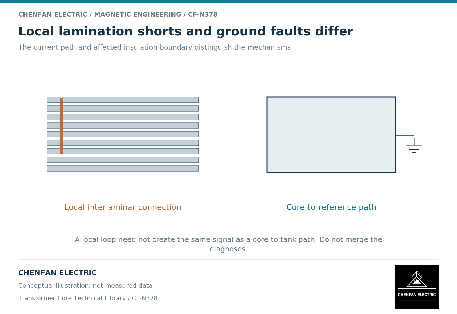
Compare the scale of the conducting path
Laminations limit electrical circulation through the steel thickness and across the stack. Unwanted interlaminar contacts can join material regions that were intended to remain separated electrically. The resulting loss depends on the path geometry and the magnetic flux linked by that path.
Lamination models distinguish bulk magnetic behavior from electrical conductivity and stacking assumptions. [1] A homogenized model may represent average behavior without resolving individual local contacts.
A core-to-tank connection belongs to a larger node network. Whether it is intended or unintended depends on the grounding design. Core-grounding research treats potential control and current paths through that network. [2] It does not turn every local lamination contact into an additional external ground.
Match the observation to the hypothesis
A local hot spot within a stack may motivate examination of interlaminar circulation, but it is not proof of the mechanism. A low-resistance path between core and tank may motivate examination of grounding topology, but its interpretation depends on the test configuration and intended connections.
The distinction is easiest to preserve in an evidence matrix.
| Evidence | Most direct question addressed | Important limit |
|---|---|---|
| Lamination coating or sample test | Material-scale insulation behavior | Not a test of every assembled contact |
| Local assembly observation | Condition at the inspected location | Concealed paths may remain unknown |
| Core-to-tank interface test | Defined assembly-node relationship | Does not resolve all interlaminar paths |
| Ground-lead monitoring | Current in the monitored route | Other local loops may not pass that sensor |
| Thermal observation | Where heating appears under a duty | Cause still requires correlation |
This prevents a single convenient test from becoming a universal core-health certificate.
Avoid conflating appearance and mechanism
A damaged edge, an insulation defect and an unwanted structural contact require different descriptions. Record the observed condition first, then identify the hypothesized electrical path. The investigation can then assess whether that path links enough changing flux to explain the loss or signal.
A model used for this purpose must retain the relevant spatial scale. A core represented as one equipotential node cannot resolve individual interlaminar loops. A detailed lamination model that omits tank and clamp connections cannot establish the complete grounding topology.
Selecting the right scale is more useful than adding detail unrelated to the suspected mechanism.
Close each boundary separately
The disposition should identify which requirement is affected: lamination condition, assembled-core magnetic performance, core-to-clamp insulation, or final core-ground topology. Link the corrective evidence to that same requirement.
No generic resistance number or burr limit is introduced here. Such criteria belong to the agreed material, drawing, test method and equipment design. Nor does this distinction authorize disconnection or modification of an installed core.
The useful conclusion is precise: an acceptable assembly-node test does not prove the absence of all interlaminar shorts, and acceptable material insulation evidence does not prove the final core-to-tank network is correct. Keeping those statements separate improves both fault investigation and supplier acceptance discussions.
References
[1] David Meeker. Finite Element Method Magnetics User Manual.
[2] Xiu Zhou and coauthors / Frontiers in Energy Research. Analytical modeling and calculation of core grounding current in converter transformer (2023).