

Split-core assemblies require an explicit electrical definition after reassembly. Mechanical contact between sections does not by itself prove the intended electrical continuity, and successful magnetic closure does not establish the grounding topology. The final design must state which sections form one core node and how they remain separated from clamps and other structures.
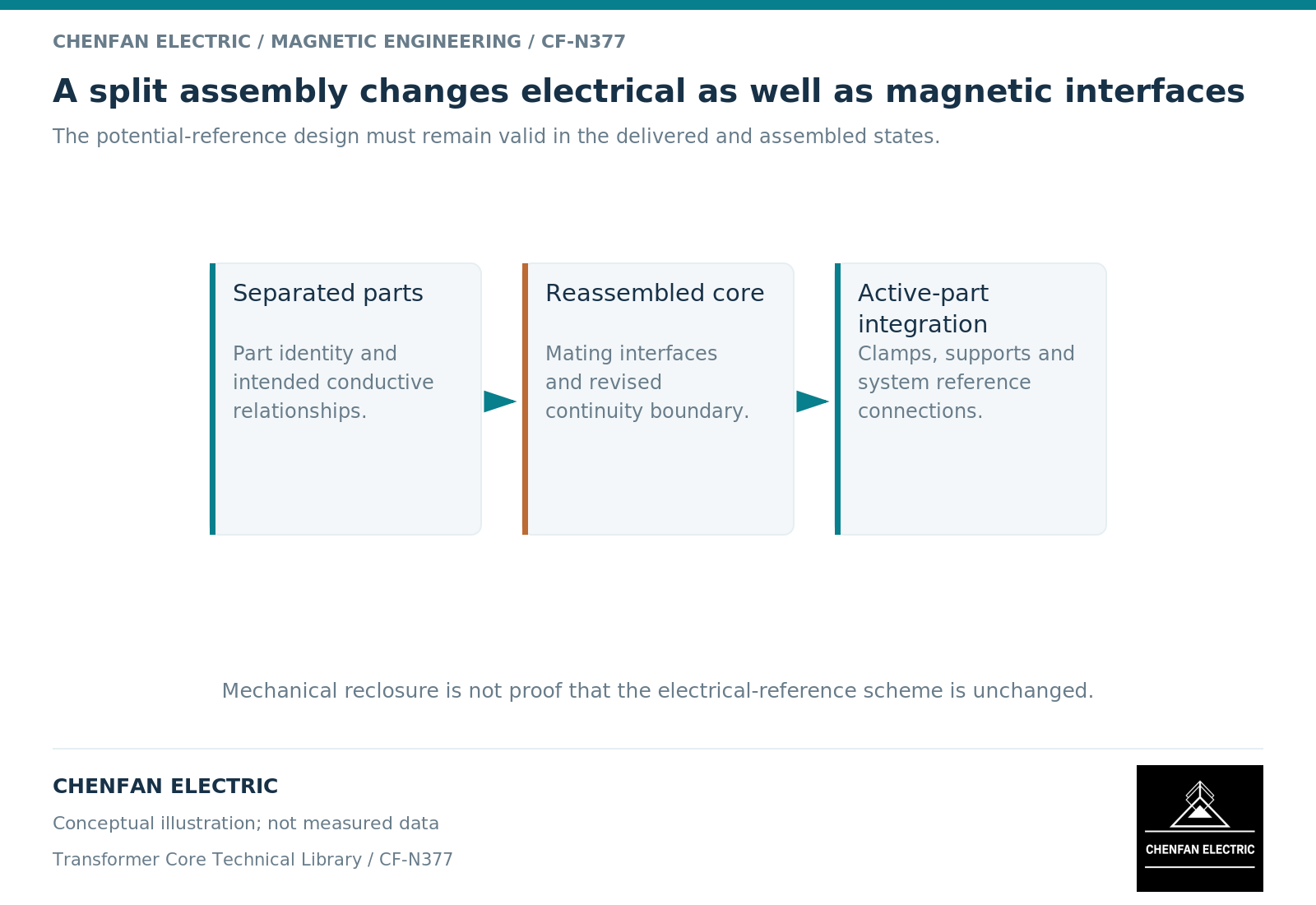
Define the delivered and assembled states separately
A core may be delivered as sections, packets or a partially assembled structure. Its transport state can differ from the state used for winding installation, testing and normal service. Each state needs a clear identity when electrical evidence is recorded.
The grounding objective remains control of the designated core node’s potential without unintended additional paths. Core-grounding studies emphasize the underlying electrical network rather than only the visible external lead. [1]
For a split assembly, identify the intended electrical grouping of the sections. Do not assume that every lamination or packet is an equipotential block simply because a simplified schematic draws the core as one node.
Keep magnetic closure and electrical continuity distinct
A magnetic joint is designed to carry flux across an interface. Its magnetic reluctance depends on geometry and material behavior. An electrical connection depends on a conducting path and its condition. These are different physical properties. [2]
An interface can provide satisfactory magnetic coupling while remaining electrically separated in a way the grounding design anticipates. Alternatively, mechanical hardware may create an electrical route that was not intended. The required arrangement must come from the controlled design, not a general assumption that “tight contact is good.”
This distinction is particularly important when assembly pressure, insulating parts or fastening arrangements change. Such changes can affect more than one function and should not be judged from one measurement alone.
Use a state-and-node record
| Assembly state | Information to retain |
|---|---|
| Delivered sections | Section identification and supplied electrical interfaces |
| Reassembled magnetic structure | Joint revision and intended node grouping |
| After clamps and supports | Added conductive paths and insulation boundaries |
| Authorized electrical testing | Actual node pair and approved configuration |
| Final active part | Confirmed service topology and evidence reference |
The record is a traceability tool, not an assembly sequence. It does not authorize testing or connection changes.
A test report should indicate whether it concerns one section, the assembled core, or the integrated active part. Combining several section reports does not automatically create a test of the final network, because assembly introduces new interfaces and possible paths.
Assign the interface owner before manufacture
The core supplier should know which electrical features belong to its scope and which are completed by the transformer manufacturer. The latter retains responsibility for the final grounding and protective-earthing design.
A change request should identify both the mechanical interface and its electrical function. If a replacement fastener or support changes the intended continuity, the review should not close merely because its strength or dimensions match.
The practical deliverable is a final-state node map tied to identified sections, drawings and verification records. It resolves the common ambiguity between magnetic assembly, mechanical assembly and electrical assembly. A split core is not inherently incompatible with a defined grounding scheme; it simply makes the interface definition and reassembly evidence especially important.
References
[1] Xiu Zhou and coauthors / Frontiers in Energy Research. Analytical modeling and calculation of core grounding current in converter transformer (2023).
[2] Lloyd Dixon / Texas Instruments. Magnetics Design 1 – Introduction and Basic Magnetics.