

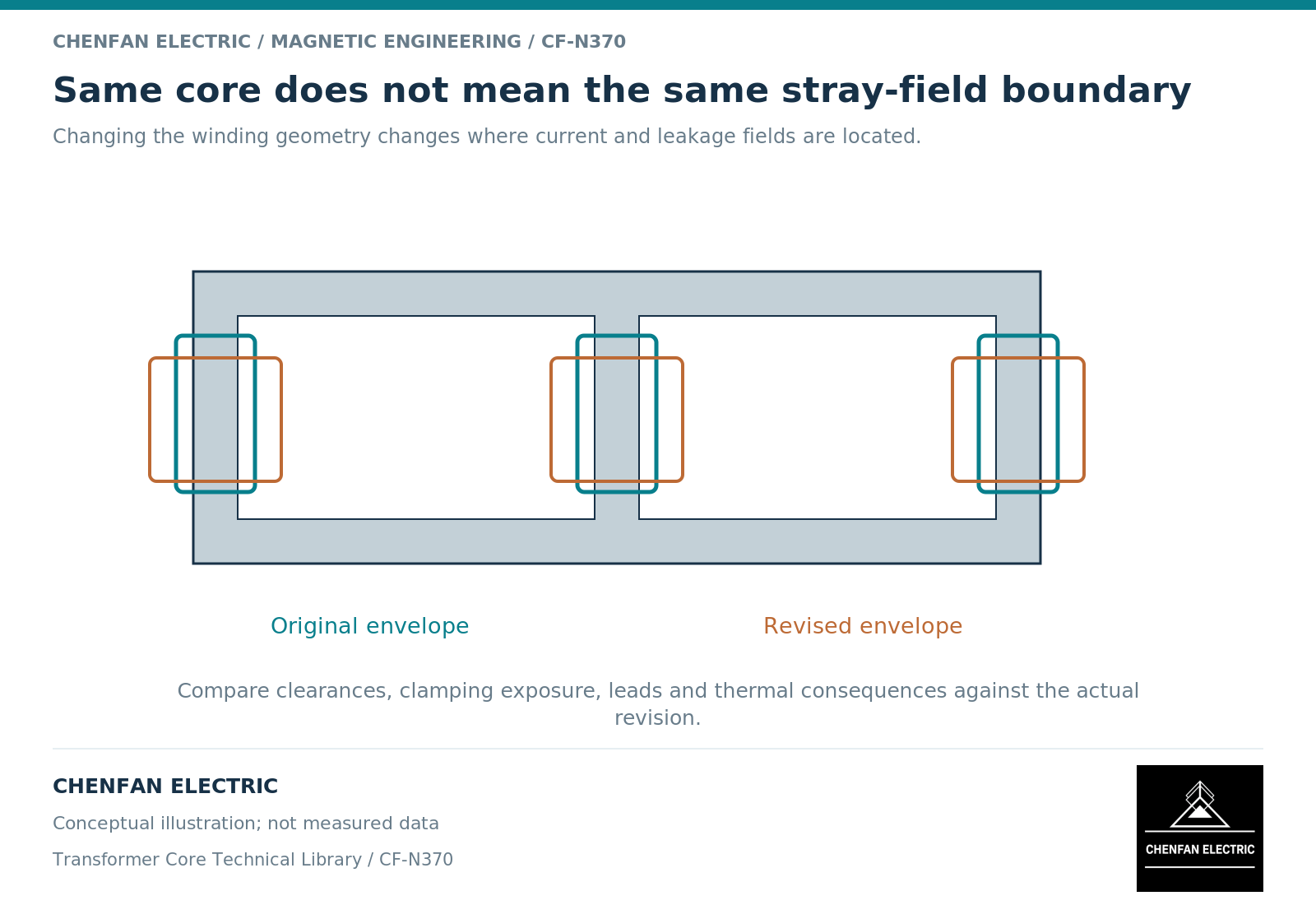
An unchanged core drawing does not establish that a revised transformer has unchanged stray-field behavior. Moving winding ampere-turns, splitting a winding or rerouting leads can alter the field seen by clamps, shields and the tank. The change review must therefore follow the active-part geometry, not only the core part number.
Separate what remains fixed from what has changed
The main magnetic operating point may remain similar when induced volts per turn and frequency are retained. That does not freeze the leakage field. Transformer design treatments link leakage behavior to the winding arrangement and incomplete flux linkage. [1]
Create a change map that distinguishes the core outline, net magnetic area and joint arrangement from winding height, radial build, axial position, interwinding gaps, tap distribution and lead routes. Mark which dimensions are truly unchanged and which are merely within a familiar outer envelope.
A winding with the same total turns and current can distribute ampere-turns differently along the limb. Equal totals do not prove equal local cancellation.
Revisit the structures exposed to the revised field
Examine winding-end clamps, tank walls, lead supports, shields and connecting hardware. A local field shift can move loss from one component to another. A comparison of total loss alone may miss that redistribution.
Conducting-region models require the actual material properties and current paths of the structures included. [2] An old thermal result should not be carried forward when its electromagnetic source distribution has changed materially.
| Design change | Review focus |
|---|---|
| Shorter winding height | End-field distribution and ampere-turn balance |
| Increased radial gap | Leakage energy and impedance |
| Unequal split-secondary loading | Spatially unbalanced current distributions |
| Relocated leads | Local exposure near supports and penetrations |
| Revised shield position | Protected region and displaced loss |
These are prompts for analysis, not predictions that every change necessarily causes a problem.
Use paired cases to isolate the effect
Compare the old and new geometries under the same defined excitation first. Then examine any newly required operating cases. This separates a geometry effect from a changed duty specification.
Preserve the winding reference side, connection, tap and current definitions across the comparison. For multiwinding equipment, identify which secondary loading combinations are included rather than using one aggregate current.
A reduced model can be used for screening when its omitted features are common to both designs and unlikely to control the difference. If the change introduces a new three-dimensional lead path or end region, that argument may no longer hold. State where additional detail is required.
Close the change at the responsible interface
The core manufacturer needs an updated core definition only when the revision affects its supplied scope or manufacturing assumptions. The transformer original equipment manufacturer still owns the complete active-part consequences, including leakage impedance, structural heating, dielectric integration and mechanical duty.
The review record should identify the revised drawings, compared operating cases, affected observables and evidence used to accept the change. An explicit “core unchanged; active-part field review updated” conclusion is more useful than either reopening every core parameter unnecessarily or declaring the entire transformer unchanged.
For Chenfan Electric core projects, this distinction keeps manufacturing change control focused while preserving the designer’s broader system responsibility. A repeated core part number supports traceability; it is not a substitute for evaluating a new winding arrangement around it.
References
[1] Lloyd Dixon / Texas Instruments. Magnetics Design 4 – Power Transformer Design.
[2] David Meeker. Finite Element Method Magnetics User Manual.