

A bushing lead should be assessed together with its return-current paths and neighboring conductors. An isolated straight-conductor field calculation can illustrate distance dependence, but it does not reproduce a transformer cover, penetration or lead assembly. Local structural heating depends on the assembled electromagnetic geometry, not just the lead’s current rating.
Use the isolated-conductor result only as a screening check
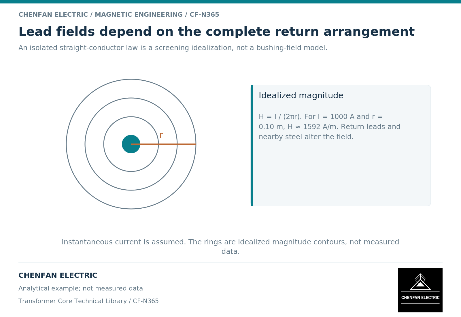
For a long straight conductor in an ideal unbounded nonmagnetic region, magnetic field strength is H = I/(2πr). Current I is in amperes and radial distance r in metres. This follows from Ampere’s law. [1] The expression excludes nearby magnetic steel, finite conductor ends and return conductors.
As an illustrative instantaneous calculation, 1,000 A at 0.10 m gives about 1,592 A/m. This is not a prediction of flux density in a steel cover or a permissible spacing. Adding a return conductor changes both field magnitude and direction at the point of interest.
A two-conductor sketch should therefore show current direction as well as separation. A three-phase arrangement should preserve the relative instantaneous currents or phasors, not add all phase-current magnitudes as if they peaked together.
Examine penetrations as three-dimensional regions
Near a cover opening, field lines and induced currents redistribute around edges and adjoining structures. The thickness and magnetic response of the plate, its electrical continuity, and the lead’s position all affect the result.
Finite-element analysis can represent conducting structures and induced-current effects, but the geometry and boundary conditions determine which paths are present. [2] A two-dimensional slice may miss a return route around a penetration or through an attached component.
The same caution applies to an apparently minor lead reroute. A change in bend radius, approach angle or phase separation may alter the local field without changing the main core drawing.
Separate four design questions
| Question | Evidence to retain |
|---|---|
| What produces the field? | Lead and return geometry with current waveforms |
| Where can induced current circulate? | Conductive connections and openings |
| Where is heat generated and removed? | Local loss map and thermal boundaries |
| Can the arrangement be built and operated safely? | Approved dielectric, mechanical and assembly definition |
A modification that appears favorable electromagnetically can conflict with insulation clearances, mechanical support, sealing or accessibility. Those constraints are not contained in a standalone magnetic calculation.
Do not turn a conceptual recommendation about current paths into a slot dimension or field retrofit instruction. Such details require the responsible transformer’s approved design and verification.
Make the lead review reproducible
Document the lead routes in the same coordinate system as the tank and active part. Identify the phase, winding, connection and operating case for each source. State whether the current value is instantaneous, peak or root-mean-square and whether harmonics are included.
For a design comparison, keep the tank material, current spectrum and thermal boundary unchanged while changing the selected geometric feature. Report both the protected region and any newly exposed adjacent region.
The result should show why a layout is acceptable within a defined operating envelope, not merely that one field plot looks less intense. This preserves the value of early analytical screening while keeping the final responsibility with the complete electromagnetic, dielectric and mechanical design.
References
[1] Lloyd Dixon / Texas Instruments. Magnetics Design 1 – Introduction and Basic Magnetics.
[2] David Meeker. Finite Element Method Magnetics User Manual.