

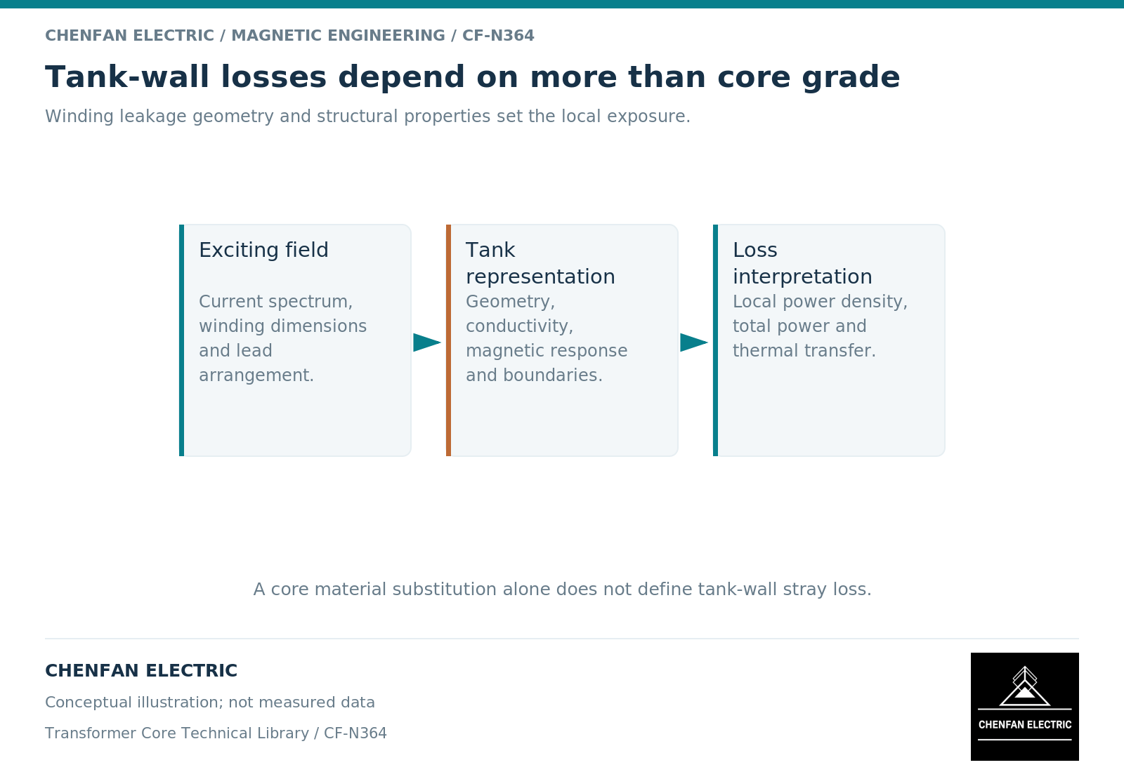
A tank-wall stray-loss model starts with the field reaching the tank, not with the loss grade of the main core steel. Winding currents, lead routes, shields, tank geometry and tank material all help determine that field and the induced-current distribution. Core-grade data may be relevant elsewhere in the model, but it cannot directly predict a tank hot spot.
Define the source and its return geometry
The main core and the winding leakage region perform different electromagnetic roles. Transformer design descriptions separate mutual coupling from leakage effects. [1] For a tank study, the locations of ampere-turns and the three-dimensional current return paths may be more important than a detailed model of every core joint.
Record the winding connection, tap, loading combination and current waveform. Include lead conductors that approach the wall or pass through a cover. A balanced total three-phase current does not mean the local field cancels everywhere near separated conductors.
A drawing revision that moves a lead without changing the core can invalidate a local tank-field comparison. Preserve source geometry as carefully as the tank outline.
Use the properties of the tank component
A solid wall has different electrical and magnetic behavior from an insulated lamination stack. Relevant inputs include conductivity, magnetic response where applicable, thickness, openings, joints and attachments. Field-model documentation distinguishes conducting regions and constitutive data rather than applying one steel-loss coefficient to every metal part. [2]
Connections can matter because a cover, flange or support may complete a larger current path. Modeling each as an isolated shape can suppress a path that exists in the assembly. Treat uncertain contacts explicitly in sensitivity cases instead of hiding them in a nominal geometry.
Skin and proximity effects are frequency dependent. A fundamental-frequency field solution is not automatically representative of a harmonic-rich operating condition, even when total root-mean-square current is unchanged.
Keep loss and temperature as separate outputs
Integrated wall loss is a power quantity. Peak surface or internal temperature depends additionally on its spatial distribution, cooling conditions, thermal interfaces and operating duration.
A small total loss concentrated near an opening can require more attention than a larger loss spread over a well-cooled area. Conversely, a high plotted local density at a geometric singularity may need mesh and averaging review before it is treated as a physical hot spot.
| Output | Supporting definition |
|---|---|
| Total wall loss | Included parts and integration volume |
| Local loss density | Coordinates, averaging and mesh sensitivity |
| Maximum temperature | Cooling boundary, duration and material properties |
| Design comparison | Same source case and reporting metric |
| Validation result | Identified measurement and matching operating state |
Release the model assumptions with the result
A useful tank-loss report includes the electromagnetic source case, conducting network, material data, mesh and domain checks, thermal boundary conditions and comparison evidence. List the structures excluded because they were judged unimportant and explain that judgment.
For preliminary design, rank candidate geometries only within the represented conditions. For a final decision, confirm that the dominant operating cases and actual lead arrangements have been included. Do not transfer a favorable result from one winding configuration to another solely because the tanks share dimensions.
When a tank hot spot is reported, this record directs the investigation toward the relevant field and heat-transfer mechanisms. It avoids the unsupported shortcut of blaming the core steel or prescribing a different grade before the source of the tank loss has been established.
References
[1] Lloyd Dixon / Texas Instruments. Magnetics Design 4 – Power Transformer Design.
[2] David Meeker. Finite Element Method Magnetics User Manual.