

A small subharmonic voltage component can produce a comparatively larger flux component because integration weights voltage by inverse frequency. Assess subharmonic excitation from its amplitude, frequency, phase and duration, not from its voltage percentage alone.
Define the component in absolute frequency
A subharmonic lies below the reference fundamental frequency. State its actual frequency as well as its ratio to the fundamental. A label such as “one-fifth component” is incomplete if the base frequency is not named.
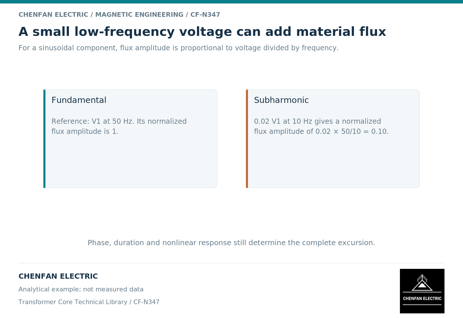
For an ideal sinusoidal induced-voltage component, flux amplitude is E_m/(2pi f N). [1] Relative to the fundamental, the flux-amplitude ratio is the voltage-amplitude ratio multiplied by the fundamental-to-component frequency ratio.
This is a screening relationship for linked flux. It assumes a defined induced voltage and turn count; it does not directly predict magnetizing current or local loss in a nonlinear coupled core.
Work through the weighting explicitly
Consider an illustrative 50-hertz fundamental and a 10-hertz component whose peak voltage is two percent of the fundamental peak. The flux-amplitude ratio is 0.02 multiplied by 50/10, or 0.10. Thus a two-percent voltage component contributes a ten-percent flux-amplitude component under the stated ideal assumptions.
The total peak depends on phase and time alignment. It is not necessarily 1.10 per unit at every cycle. Over the combined waveform period, the slow component can shift the operating region of successive fundamental cycles.
These values are analytical examples, not a statement that such a waveform is present or permitted in any particular installation. The actual source and persistence of the component must be established from system data.
Distinguish a subharmonic from drift and bias
A resolved low-frequency alternating component is different from a constant offset, a decaying transient or measurement baseline drift. A short record may not distinguish them reliably.
Retain enough observation time to characterize the relevant low-frequency behavior, while documenting the processing method. Removing a baseline indiscriminately can erase a genuine component; retaining an instrument offset can invent one.
The magnetic model should reflect the intended trajectory. A single-frequency effective model does not automatically represent the changing state created by a superimposed slower component. [2] Nonlinear and history-dependent effects may require a time-domain treatment.
Assess the sequence of operating cycles
The slow component can make successive fundamental cycles unequal. Report the largest positive and negative excursions over the complete observation or study interval, not only one convenient cycle.
Where the duty persists, evaluate the corresponding losses and thermal behavior. A peak-flux screen can identify a concern but cannot establish a temperature limit. Winding and structural effects may also need separate analysis.
| Required input | Interpretation enabled |
|---|---|
| Component frequency | Correct inverse-frequency weighting |
| Voltage amplitude and phase | Reconstruction of the combined trajectory |
| Duration and stationarity | Distinction between sustained and transient duty |
| Measurement baseline treatment | Separation of real low-frequency content from drift |
| Core and winding model | Nonlinear response to the reconstructed excitation |
The resulting technical request should specify the waveform envelope rather than an isolated distortion percentage. This gives the transformer designer a meaningful excitation boundary and prevents a small voltage number from being dismissed before its magnetic significance has been calculated.
References
[1] Lloyd Dixon / Texas Instruments. Magnetics Design 1 – Introduction and Basic Magnetics.
[2] Nirmal Paudel / COMSOL. Model Magnetic Materials in the Frequency Domain with an App (2016).