

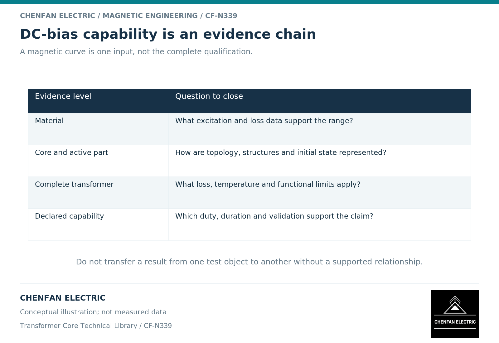
A direct-current-bias capability statement requires evidence about the complete transformer under a defined duty. A magnetization curve is necessary for some models, but it does not establish winding heating, structural hot spots, harmonic response or acceptable duration by itself.
Define the claim before collecting evidence
The phrase “DC-bias capable” is incomplete. Specify the affected winding, current definition, polarity or time variation, alternating voltage, frequency, tap, load and duration. State the performance quantity being qualified.
A statement about acceptable temperature is different from one about reactive demand or harmonic current. A design can meet one criterion while requiring further review against another. Keep the criteria separate so that a favorable result is not broadened after the assessment.
Quasi-direct-current studies illustrate the connection between bias, nonlinear excitation and system effects, but their case results do not qualify an unrelated transformer. [1]
Build an evidence chain across four boundaries
Material data establish the constitutive input under their test conditions. Core geometry establishes branch areas, paths and directional orientation. The active-part and structural model establishes winding coupling and local loss regions. The thermal model establishes temperature under the specified duty and cooling conditions.
Each boundary needs its own evidence. A steel certificate cannot validate a tank-loss model. A total-loss measurement cannot locate every hot spot. A thermal calculation cannot compensate for an incorrect excitation current definition.
History-dependent and nonlinear magnetic models also require an identified range of support. [2] If the bias assessment relies on extrapolation beyond measured data, that should be visible in the uncertainty and validation record.
Distinguish qualification methods
| Method | Useful evidence | Important limitation |
|---|---|---|
| Direct test | Observed response of the tested configuration | Limited to the tested duty and measurement coverage |
| Validated calculation | Traceable model checked against relevant data | Depends on parameter and model-form support |
| Design comparison | Relationship to an already evaluated design | Requires justified similarity in controlling features |
| Material-only review | Constitutive screening | Does not qualify complete-transformer heating |
The assessment may combine these methods. NERC’s October 2017 thermal-impact white paper describes time-domain thermal response and manufacturer capability curves as distinct assessment routes. [3] A peak current alone does not specify the temperature response. This is historical methodological evidence, not a current pass/fail criterion or a Chenfan product rating. The final statement must explain which parts are measured, calculated or inferred.
A comparison with another design should identify the features that remain equivalent: topology, winding ampere-turns, structural geometry, cooling and operating envelope. Similar power rating or the same material family is not enough.
Write the qualified envelope and exclusions
The final capability note should name the design revision and the evaluated cases. Include the controlling result, acceptance basis and any restrictions on duration, loading or configuration. Avoid a single current limit without its conditions.
Also state which changes trigger reassessment. A new tertiary connection, altered tank spacing, different cooling arrangement or revised winding geometry can affect the response even when the main core section is unchanged.
For Chenfan Electric’s core supply, the documented contribution is the agreed core geometry, material identity and contracted verification. Complete-transformer bias qualification remains a broader engineering responsibility. Keeping that scope explicit protects the buyer from unsupported assurances and gives the core manufacturer a clear technical definition to build against.
References
[1] Jessica Wert and coauthors. The Effects of Correctly Modeling Generator Step-Up Transformer Status in Geomagnetic Disturbance Studies (2022).
[2] Cesare Tozzo / COMSOL. Modeling Ferromagnetic Materials in COMSOL Multiphysics.
[3] North American Electric Reliability Corporation (NERC). Transformer Thermal Impact Assessment White Paper (October 2017).