

A geomagnetically induced current study needs transformer connection and resistance data as well as magnetic and thermal information. Nameplate power alone is insufficient. The system model establishes where quasi-direct current can flow; the transformer assessment establishes what that current does to a particular design.
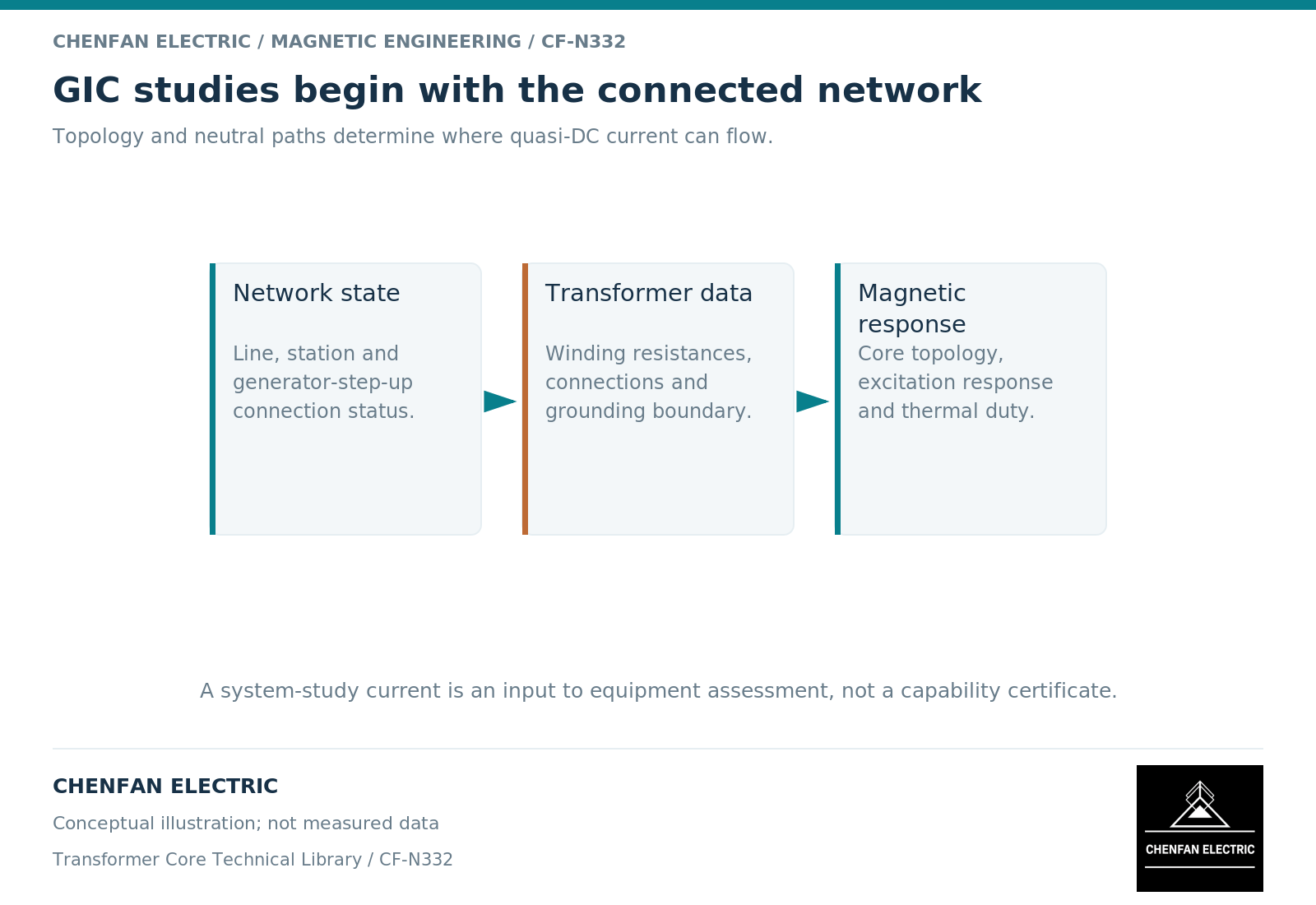
Keep network flow and equipment response separate
Geomagnetically induced currents, or GICs, are low-frequency currents driven through available network and grounding paths during geomagnetic disturbances. Their transformer effects depend on the connected windings and resulting magnetic excitation. [1]
The system calculation therefore needs the actual electrical topology, including which transformers and neutral paths remain connected in each scenario. A generator being unavailable does not, by itself, establish the associated transformer’s connection state. Research comparing alternative generator step-up transformer statuses demonstrates why that distinction can affect GIC results. [1]
This article does not forecast a storm, assign regional risk or quote a current regulatory screening threshold. It defines the transformer data boundary needed for a defensible study.
Define every current before comparing it
Neutral current, winding current and an effective per-phase GIC quantity are different labels. The conversion depends on the transformer connection and the study convention. An autotransformer also requires careful treatment of series and common winding contributions.
For each current field, state units, sign convention, winding identity and whether it represents a measured neutral value or a model-derived effective quantity. Avoid a spreadsheet column simply titled “DC amps.”
Resistance data need a stated basis as well. Identify winding paths, relevant temperature assumptions and grounding-path information supplied by the system owner. Do not substitute an alternating-current leakage reactance for the direct-current resistance used in the network path.
Link the current to magnetic and thermal evidence
The transformer model needs core topology and the nonlinear response relevant to biased operation. A geometrical magnetic representation distinguishes shared and return branches. [2] A generic independent-phase model should not silently stand in for every construction.
The next layer is the equipment response: additional reactive demand, harmonic currents and losses in windings or structural regions. Thermal assessment needs current history, loading, initial temperature and cooling assumptions. NERC’s October 2017 thermal-impact white paper separately considers winding and metallic-part hot spots and their time-dependent responses. [3] It is used here as historical technical guidance, not as a statement of current regulatory thresholds.
| Data owner | Typical contribution |
|---|---|
| System-study team | Network topology, induced-field scenario and current paths |
| Asset owner | Actual connection status, neutral arrangement and operating cases |
| Transformer designer | Winding definitions, topology and response characteristics |
| Thermal specialist | Loss-to-temperature model and duty interpretation |
These roles may overlap, but the input responsibility should remain explicit.
Handover a scenario-based dataset
Provide a base transformer record plus separate scenario records for connection status, loading and current history. This prevents one assumed operating state from being reused inadvertently across every system case.
Mark each field as measured, design-derived, estimated or unavailable. Where uncertainty materially changes the result, retain a sensitivity range. A model can still be useful with uncertain data if the uncertainty is visible and propagated appropriately.
A capability statement should identify the complete design and evaluated duty. It should not be inferred from steel grade, limb count or a generic magnetization curve alone. For core-related procurement, the useful output is the magnetic envelope and geometry definition supplied to the core manufacturer, while the complete-transformer and network conclusions remain with the responsible design and system teams.
References
[1] Jessica Wert and coauthors. The Effects of Correctly Modeling Generator Step-Up Transformer Status in Geomagnetic Disturbance Studies (2022).
[2] Manitoba Hydro International / PSCAD. The UMEC Approach.
[3] North American Electric Reliability Corporation (NERC). Transformer Thermal Impact Assessment White Paper (October 2017).