

Return-limb saturation during unbalanced operation must be checked from the instantaneous flux in each return branch, not from the balanced wound-limb rating alone. The controlling branch can change with the combination of phase components and with the available magnetic return paths.
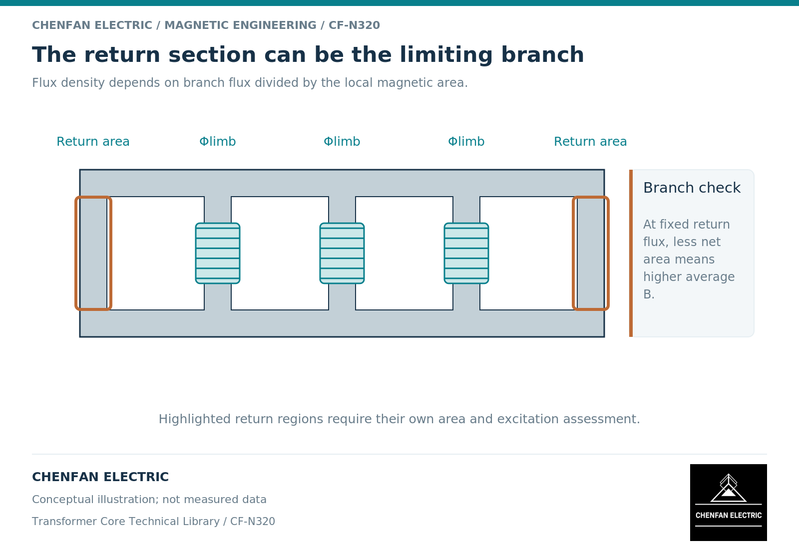
Trace the combined branch duty
In a five-limb construction, outer limbs return combinations of the flux carried by the wound limbs. A zero-sequence component contributes an in-phase sum. Balanced components impose a different spatial distribution. Shared-branch magnetic models represent these combinations through the actual topology. [1]
The important quantity is therefore Phi_branch(t), followed by B_branch(t) = Phi_branch(t)/A_net for a suitably defined average section. The net area must belong to that branch. Using the wound-limb area for a narrower return branch can hide its higher density.
A single scalar “core flux” is inadequate when the purpose is to identify the most heavily excited branch. Keep the limb and yoke names used in the drawing so that the result can be traced back to geometry.
Add components in time, not by unrelated peaks
Suppose an illustrative branch waveform contains a sinusoidal component of amplitude 1.0 per unit and a second component of amplitude 0.2 per unit. Its actual maximum depends on their relative phase and frequency. The arithmetic sum 1.2 is an upper bound for those component amplitudes, not proof that the waveform reaches it.
For an offset component, polarity matters as well. One half-cycle may move closer to the nonlinear region while the other moves away. Report both positive and negative extrema instead of only an absolute average or a root-mean-square value.
The response near saturation cannot be described solely by a constant permeability. A constitutive model must reflect the intended nonlinear behavior and, when necessary, magnetic history. [2] The selected definition of a saturation threshold should be stated rather than implied by a color change in a plot.
Check what redistributes when a branch stiffens magnetically
As a branch’s incremental permeability falls, the surrounding magnetic network can redistribute flux. External regions and alternative iron paths may take a different share. A calculation that independently clips each limb at a chosen density does not conserve the coupled response automatically.
This is why the review should include winding currents and terminal conditions as well as branch fluxes. The circuit can change the driving ampere-turns while the magnetic network changes the return distribution. A fixed-voltage assumption and a fixed-current assumption may lead to different interpretations.
For a local structural-heating assessment, the redistributed field must then be followed into the relevant conducting parts. A branch saturation result alone does not locate a tank or clamp hot spot.
Use a branch-by-case review sheet
List each wound limb, outer limb and critical yoke section against the operating cases: balanced excitation, specified unbalance and relevant transient or biased conditions. For each entry, record area basis, waveform extrema, nonlinear-model range and evidence origin.
Keep the source of each result visible. Material curves support constitutive behavior; geometry supports branch areas and lengths; assembled-transformer tests support the observed response under their connection. None should be relabeled as evidence for all the others.
The resulting decision is concrete: which branch controls, under which case, and what design or operating assumption sets that limit? That is more useful than declaring the entire core “saturation resistant.” It also gives the core manufacturer a precise geometry question instead of an unsupported request to guarantee the complete transformer’s behavior under unspecified unbalance.
References
[1] Manitoba Hydro International / PSCAD. The UMEC Approach.
[2] Cesare Tozzo / COMSOL. Modeling Ferromagnetic Materials in COMSOL Multiphysics.