

Zero-sequence inductance is meaningful only with its operating level, definition and connection. A single number cannot describe every point of a nonlinear magnetic response. Before comparing values, establish whether they represent a small perturbation, a finite-amplitude cycle or an equivalent impedance derived from a terminal test.
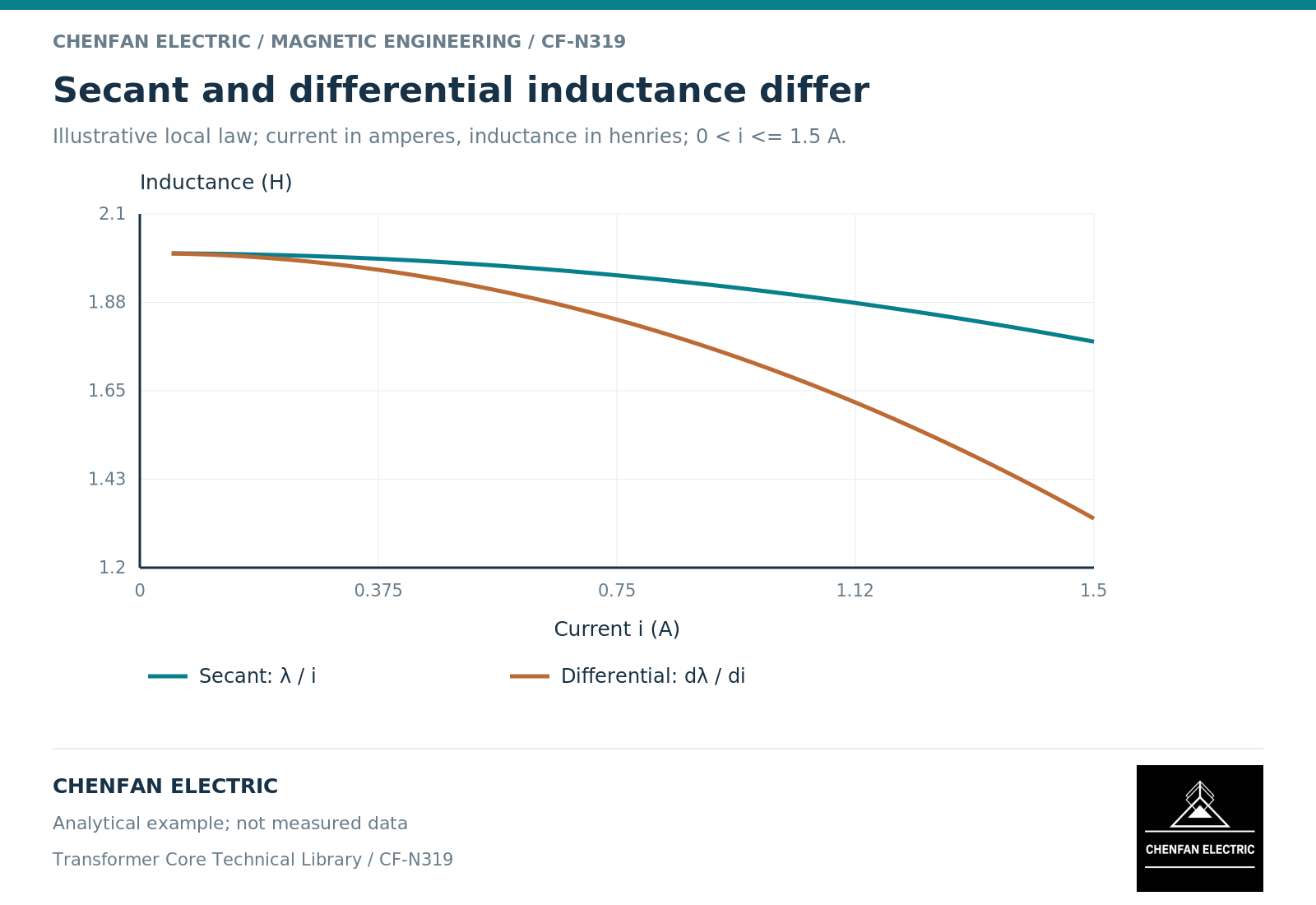
Inductance can describe different slopes
For a single-valued flux-linkage curve lambda(i), secant inductance is lambda/i relative to a defined origin, whereas differential inductance is the tangent d(lambda)/di. Linearized models often use “incremental” for that differential small-signal response. [3] For a finite excursion, state the actual Delta lambda/Delta i or AC impedance definition instead of assuming it is the same tangent.
With hysteresis, the response also depends on the trajectory, bias, excursion amplitude and frequency. A measured small-signal response can involve a minor loop and must not be identified automatically with a tangent to the normal magnetization curve. Ferromagnetic-model guidance distinguishes single-valued and history-dependent constitutive choices. [1]
An illustrative local model makes the difference clear. Let lambda = (2 H)i – (0.1 H/A²)i³ over 0 < i <= 1.5 A, with lambda in weber-turns. At i = 1 A, the secant value is 1.9 H and the differential value is 1.7 H. This invented expression is not a transformer characteristic and must not be extrapolated into a physical saturation curve. It simply shows why two valid definitions can give different numbers.
A terminal equivalent includes its circuit
A zero-sequence test or model may produce a terminal impedance rather than a pure magnetizing inductance. Winding leakage, resistance, other closed winding circuits and neutral connections can contribute to that result.
Core topology determines which magnetic return branches participate. A model that includes geometrical coupling can distinguish those paths; an independent-phase model may not. [2] The connection and topology must therefore accompany the numerical value.
Also establish the frequency and waveform. Converting reactance to inductance through L = X/(2pi f) assumes that the reported X has a meaning compatible with that conversion. Applying it blindly to a strongly distorted nonlinear waveform can conceal the definition used to extract the equivalent reactance.
Compare a curve of defined quantities
For nonlinear work, request values or waveforms across the operating range relevant to the project. Keep the extraction method unchanged at each point. Mixing an incremental value at low excitation with a fundamental-frequency equivalent at high excitation creates a curve that has no single interpretation.
| Label on the result | Additional definition needed |
|---|---|
| Magnetizing inductance | Flux-linkage basis, state and slope definition |
| Zero-sequence reactance | Frequency, connection and extraction method |
| Per-unit impedance | Voltage and power bases, reference winding |
| Saturated inductance | Evaluated range and treatment of leakage |
The comparison should include repeatability and uncertainty where available. A difference smaller than the measurement or identification uncertainty should not be promoted into a design advantage.
State the intended use of the value
A value intended for a linear fault calculation may be entirely appropriate within that study’s assumptions. It should not then be copied into a transient model as the slope for every instant. Conversely, a detailed nonlinear curve may contain more information than a particular network study needs.
The practical handover is a definition sheet: terminal configuration, excitation range, frequency, temperature or conditioning where relevant, reference bases and intended model use. Attach the raw or processed evidence used to derive the value.
This approach turns an apparent disagreement between suppliers or software packages into a solvable question. First align what “inductance” means. Only then decide whether the remaining difference reflects the transformer, the operating state or the modeling method.
References
[1] Cesare Tozzo / COMSOL. Modeling Ferromagnetic Materials in COMSOL Multiphysics.
[2] Manitoba Hydro International / PSCAD. The UMEC Approach.
[3] QuickField / Tera Analysis. Apparent and incremental magnetic permeability.