

Unbalanced magnetic excitation can send flux into structural return regions and create losses outside the main core. To assess tank heating, request evidence that connects the excitation waveform to the structural loss distribution and then to temperature. Neither a core-steel certificate nor a single no-load loss value completes that chain.
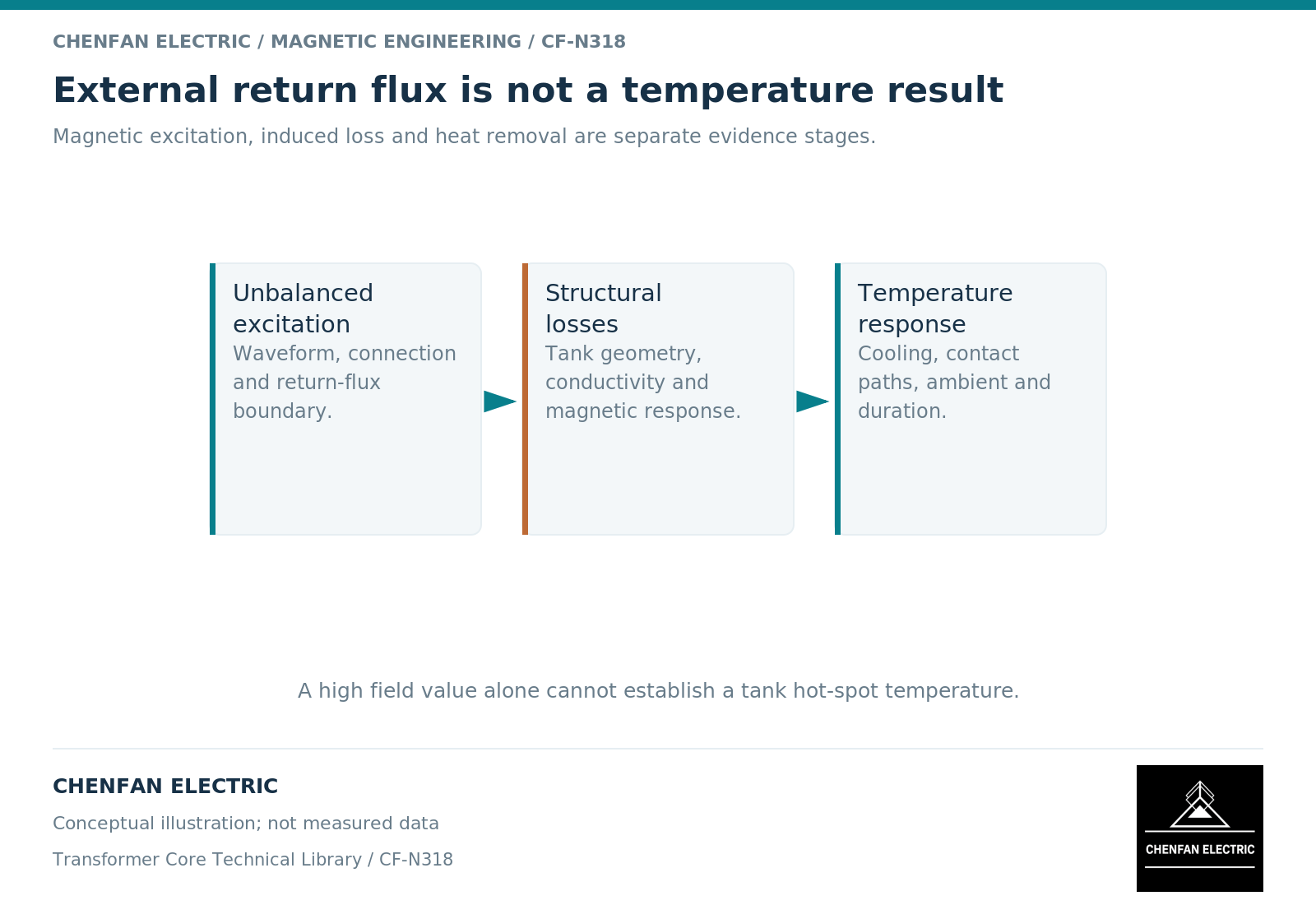
Identify which field is being investigated
There are at least two distinct questions: net return flux associated with a zero-sequence or other non-cancelling magnetic component, and leakage fields associated with winding currents. A pure centered negative-sequence set still has zero instantaneous phase sum; unbalance alone does not prove an external main-flux return. Both main-flux return and leakage fields can interact with structural metal, but they should not be combined into an unexplained “stray flux” allowance.
A three-limb core‘s external return differs from the outer iron branches available in a five-limb construction. A magnetic-network model can help establish the relevant branch excitation. [1] It does not, by itself, locate the tank regions where conducting currents concentrate.
Ask the analyst to name the source of the structural field and the operating case that drives it. If the source is a zero-sequence component, the winding connections and neutral conditions belong in the evidence. If it is winding leakage, the current distribution and active-part geometry are essential.
Require a loss map, not only a field picture
A high flux-density region and a high-loss region need not be the same location. Conductivity, field direction, penetration, local geometry and frequency affect induced-current dissipation. The electromagnetic formulation must represent the mechanisms used to calculate that loss. [2]
A credible result identifies the modeled tank plates, clamps, shields and nearby conductors. It explains whether joints or discontinuities are represented and how material properties were selected. A smooth contour plot is not evidence of mesh convergence or correct excitation.
Integrated structural loss is useful for an energy balance, while local loss density is important for hot spots. Request both when local temperature is the decision variable. A small total loss can still be concentrated in a poorly cooled region.
Preserve duration and cooling conditions
Temperature depends on where heat is generated, how long the duty lasts and how heat leaves the region. A short transient, a repeated intermittent condition and a sustained unbalance can require different thermal treatment even if their instantaneous electromagnetic peaks are similar.
The thermal model should state initial temperature, fluid or air conditions, heat-transfer assumptions and the surrounding thermal paths. If those inputs are uncertain, show their influence rather than reporting a single temperature with unjustified decimal precision.
| Evidence | Supports | Does not independently establish |
|---|---|---|
| Branch-flux calculation | Magnetic excitation boundary | Local structural dissipation |
| Electromagnetic loss map | Heat-source distribution | Final temperature |
| Thermal model | Temperature under stated conditions | Untested duty duration |
| Measured thermal comparison | The observed configuration and case | Every alternative enclosure |
Ask for a traceable qualification statement
The final statement should identify the complete transformer configuration, excitation envelope, duration and acceptance basis. It should also say whether the conclusion is measured, calculated or inferred by comparison with a qualified design.
Changes to tank spacing, wall material, shields or winding placement can invalidate part of the evidence even when the core drawing remains unchanged. Record those changes against the model revision. Do not treat an unchanged steel grade as proof that structural heating is unchanged.
For Chenfan Electric’s core-related technical handover, the useful contribution is accurate core geometry and material identification within the agreed supply scope. The original equipment manufacturer’s structural and cooling design supplies the remaining boundary. A tank-heating claim should only follow when those pieces are joined and the complete duty has been evaluated.
References
[1] Manitoba Hydro International / PSCAD. The UMEC Approach.
[2] David Meeker. Finite Element Method Magnetics User Manual.