

Single-phase excitation of a three-phase core is a different magnetic boundary from balanced three-phase operation. Interpret it using the energized winding, the state of every other winding and the available return paths. Do not compare its current directly with a balanced no-load current as though only the number of energized phases had changed.
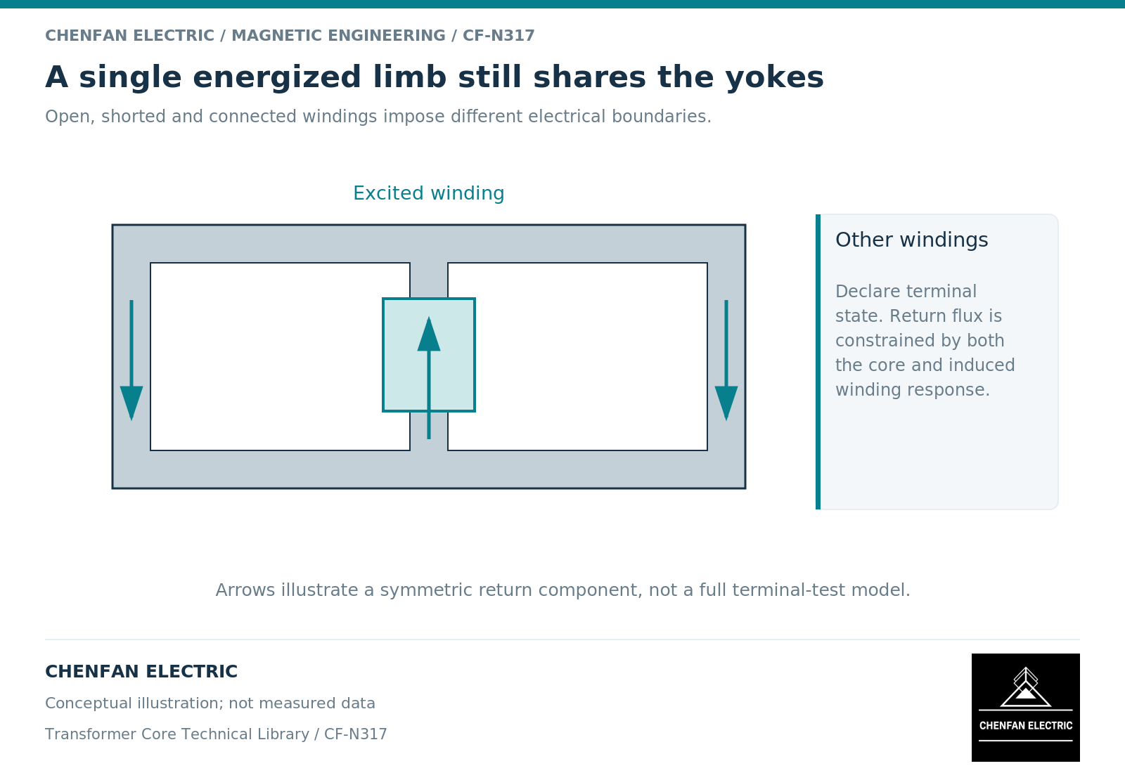
The return branches are not equally excited windings
When one limb is driven, its linked flux must return through other available branches. In an ideal symmetric three-limb illustration, excitation on the central limb can divide between two similar outer return paths. Excitation on an outer limb encounters a different geometric arrangement. Actual branch reluctances and winding responses determine the division.
This explains why a diagram of three equal, independent phase inductors can miss the behavior of a shared core. Magnetic coupling follows the physical paths, not merely the number of phase terminals. Geometrical equivalent-circuit models retain that distinction. [1]
The illustration should not be converted into a universal ratio between phase currents. Real cores have joints, unequal path lengths, nonlinear material response and winding circuits that can alter the result.
Record the complete terminal state
An unenergized winding is not a complete electrical description. It may be open, shorted, connected in a closed delta or attached to another circuit. Each condition changes the available induced-current response.
Polarity and turn count also matter. An induced voltage on another winding is evidence of linked flux, but its interpretation requires the winding relationship. A terminal label alone does not identify the relevant magnetic branch.
A comparison record should therefore include a connection diagram and the actual test object: bare core with temporary excitation, assembled active part or complete transformer. These are not interchangeable configurations. A temporary winding arrangement can characterize a magnetic assembly without reproducing every circuit present in the finished product.
Compare like-for-like observables
Suppose two records show different excitation currents for nominally the same applied voltage. Before attributing the difference to core condition, compare frequency, waveform, energized phase, turns, residual state and other winding connections. Also confirm whether the reported current is peak, root-mean-square or a selected harmonic.
The flux-producing voltage can differ from terminal voltage when winding drops are material. Saturation modeling shows why the position of the magnetizing branch relative to leakage elements matters. [2] That distinction becomes more important when the response is strongly nonlinear.
| Observation | Necessary context |
|---|---|
| Unequal phase currents | Energized limb and return-path geometry |
| Different induced voltages | Turns, polarity and winding connection |
| Changed low-level response | Magnetic history and measurement repeatability |
| High current at one level | Waveform, circuit drops and nonlinear characteristic |
This table is an interpretation framework, not a test procedure. It specifies no energization settings or safe connection sequence.
Make the conclusion narrower than the evidence
A controlled repeat of the same configuration can support a comparison over time. A change between different configurations may instead reveal a changed boundary. The report should distinguish those possibilities before assigning a fault mechanism.
For design verification, state the model prediction under the exact single-phase connection and compare the corresponding measured quantity. Agreement does not automatically validate balanced operation, zero-sequence heating or every switching transient. Each uses a different combination of magnetic and electrical conditions.
The useful outcome is a reproducible statement: this identified assembly, excited through this winding under this defined circuit state, produced this response. That is a sound basis for engineering review. A bare current number labeled “single-phase core test” is not.
References
[1] Manitoba Hydro International / PSCAD. The UMEC Approach.
[2] Manitoba Hydro International / PSCAD. The Classical Approach.