

Representing a transformer tank as a magnetic return branch is a deliberate simplification. It can be useful for a zero-sequence terminal model, but it is not equivalent to calculating the field and losses in a real tank. Decide which observable the model must reproduce before choosing that boundary.
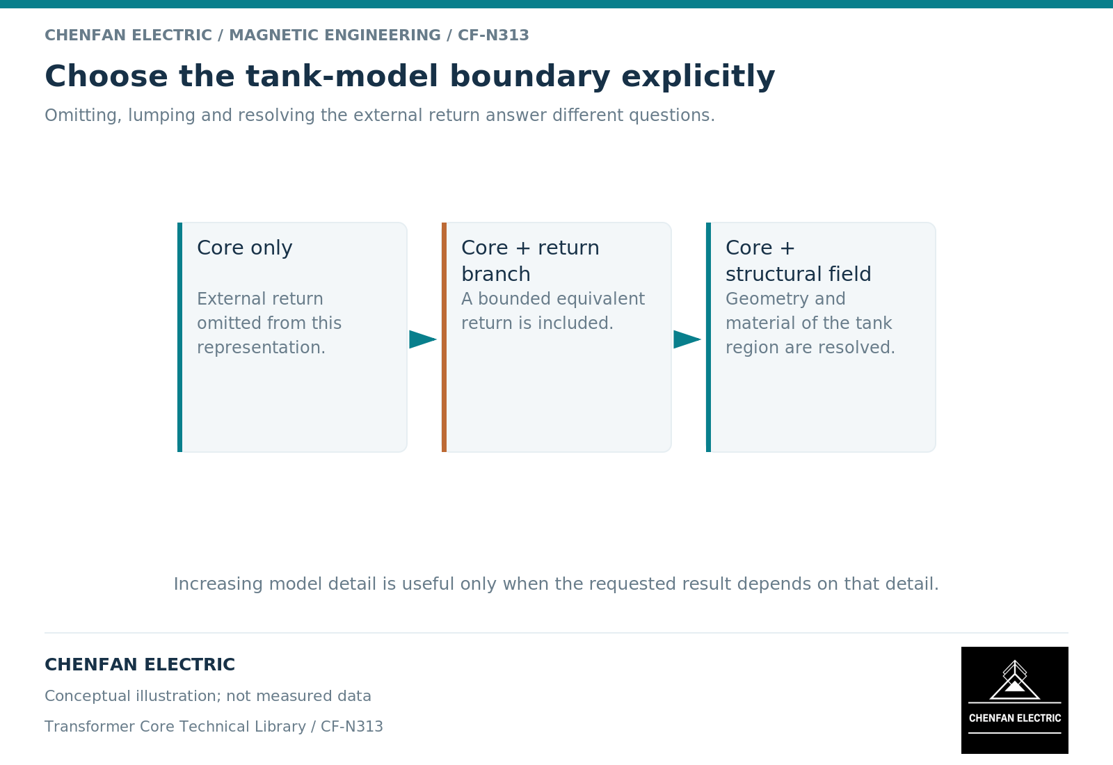
A lumped branch answers a lumped question
A magnetic equivalent circuit replaces distributed field behavior with branches. An effective reluctance can account for a return outside the main core without retaining every wall, flange and air region. Its parameters may be derived from geometry, identified from measurements or adjusted within a model-calibration process. Geometrical core models illustrate how branch choices encode magnetic coupling. [1]
The meaning of the fitted branch must remain explicit. If a parameter absorbs several omitted effects, it should not later be interpreted as the measured permeability of one steel plate. A good terminal fit can coexist with a poor physical allocation of internal flux.
This distinction is particularly important when a model is transferred between engineers. A label such as “tank inductance” sounds physical, but the implemented element may represent the entire external return region rather than the tank alone.
Separate magnetic guidance from eddy-current response
Structural steel can guide flux through its magnetic properties and oppose time-varying fields through induced currents. Those mechanisms depend on different material quantities and geometric features. A single real-valued reluctance does not automatically retain both.
A field formulation can include permeability, electrical conductivity and excitation frequency, subject to its assumptions. A magnetostatic solution, a harmonic eddy-current solution and a nonlinear transient solution are different models even when they use the same mesh. The finite-element manual makes these formulation and material distinctions explicit. [2]
For a heating question, the required output is spatial power dissipation followed by a thermal assessment. Assigning all omitted electrical loss to a magnetic branch may improve a terminal fit without locating where that heat is generated.
Choose the boundary through a model-purpose table
| Intended result | Acceptable simplification to examine | Result not established automatically |
|---|---|---|
| Terminal response in a limited range | Calibrated external return branch | Local wall flux density |
| Sequence-network behavior | Connection-specific equivalent impedance | Nonlinear transient waveform |
| Structural loss distribution | Conducting field model with actual geometry | Temperature without thermal conditions |
| Local temperature | Coupled loss and heat-transfer model | Performance outside the evaluated duty |
The table is a selection aid, not permission to use an unvalidated model. The appropriate simplification depends on whether the omitted behavior materially changes the decision.
A practical sensitivity check varies the external return representation within a defensible range. If the network conclusion barely changes, additional geometric detail may offer little value for that question. If a local loss maximum moves substantially, the same simplification is unsuitable for a hot-spot claim.
Document what was absorbed into the parameter
The handover should state the modeled structures, omitted structures, parameter-identification method and comparison data. Include the winding connection and excitation level used during calibration. Preserve the physical units and the reference side for any equivalent electrical element.
Also identify what happens when the tank geometry changes. A parameter fitted to one enclosure should not be copied to a different wall spacing or structural arrangement without review. Even when the core itself is unchanged, the external return region is not.
The useful engineering conclusion is bounded: the simplified return reproduces specified observables over specified cases. That statement is more valuable than claiming that the model “includes the tank” while leaving its actual electromagnetic meaning undefined.
References
[1] Manitoba Hydro International / PSCAD. The UMEC Approach.
[2] David Meeker. Finite Element Method Magnetics User Manual.