

Compare limb flux under unbalanced voltage by integrating the induced voltage of each phase on a common time base. Do not infer the flux imbalance directly from line-current imbalance. Load current, winding connections and leakage drops can change the relationship between terminal quantities and core excitation.
Begin with the voltage that links the core
For a winding with N turns, the induced voltage satisfies e(t) = N dPhi/dt. Integrating e(t)/N gives the change in linked flux. Terminal voltage can approximate induced voltage when the omitted drops are insignificant for the question, but that approximation becomes less reliable under heavy current or saturation. [1]
Record the voltage reference: phase-to-neutral, phase-to-phase or a directly measured winding voltage. The phase winding of a delta connection does not see the same voltage definition as the phase winding of a star connection. Applying a line-voltage record to the wrong turn count creates an error before any magnetic modeling begins.
Each phase also needs the same polarity convention. An inverted measurement channel can create an apparent zero-sequence component that is entirely artificial.
Compare waveforms rather than three headline values
A useful comparison retains positive and negative extrema, their times, and the cycle-to-cycle evolution. Three root-mean-square voltage values cannot reveal all of those features. Waveform distortion and phase displacement can alter the integrated result even when the displayed voltage magnitudes appear similar.
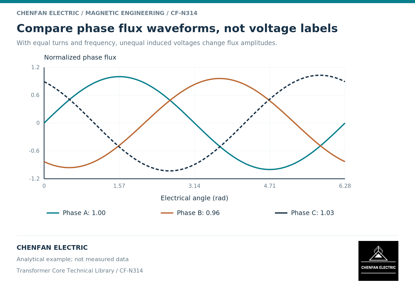
For an illustrative sinusoidal case with unchanged frequency and turns, induced phase-voltage amplitudes of 1.00, 0.96 and 1.03 per unit give flux amplitudes in the same ratios. That statement assumes centered steady-state waveforms. It does not establish the offset flux following a disturbance or the waveform in a saturated core.
Once the phase fluxes are reconstructed on consistent area, polarity and initial-state bases, calculate their instantaneous sum. For centered sinusoidal components, both a pure positive-sequence set and a pure negative-sequence set sum to zero. Unbalance therefore does not automatically imply zero-sequence flux. A nonzero sum identifies a net return requirement outside the three wound limbs; its interpretation must retain any initial flux offsets and the shared-core return model. [2]
Keep amplitude, sequence and offset distinct
| Feature | What to inspect | What it does not prove |
|---|---|---|
| Different phase amplitudes | Per-phase induced-voltage integrals | A particular structural hot spot |
| Nonzero phase sum | Common-time signed flux components | A neutral-current magnitude by itself |
| Flux offset | Initial state and transient integration | Persistent direct-current injection |
| Different current peaks | Circuit and magnetizing response | Equal percentage flux differences |
This separation avoids a common diagnostic shortcut: calling every asymmetric current trace “unequal core flux.” A nonlinear magnetizing curve can produce a large change in current for a relatively small change in peak flux. Current is an important response, but not a linear flux indicator near saturation.
A model comparison should therefore show both flux and current, with the assumptions connecting them. Hiding the flux reconstruction behind a single current plot makes it harder to distinguish excitation, material response and external-circuit effects.
Build a repeatable comparison record
Retain the original voltage records, channel scaling, time alignment, winding turns and tap position. State how winding drops, integration drift and initial flux were treated. Report the observation interval rather than selecting only the most dramatic cycle.
For the core manufacturer, the useful downstream result is the required branch-flux envelope and the geometry revision to which it applies. The manufacturer should not be asked to infer an entire unbalanced operating condition from three current values in an email.
A credible comparison ends with a defined difference: which limb, which waveform feature, under which connection and voltage condition. It does not convert an unbalanced measurement automatically into a material defect or a universal core-design limitation.
References
[1] Manitoba Hydro International / PSCAD. The Classical Approach.
[2] Manitoba Hydro International / PSCAD. The UMEC Approach.