

A magnetic shunt deliberately changes a transformer’s flux distribution or coupling. It is not necessarily evidence of a defective core. The review should identify which field the shunt is intended to influence, the required electrical characteristic and the losses or forces created in the surrounding assembly.
Identify the intended magnetic route
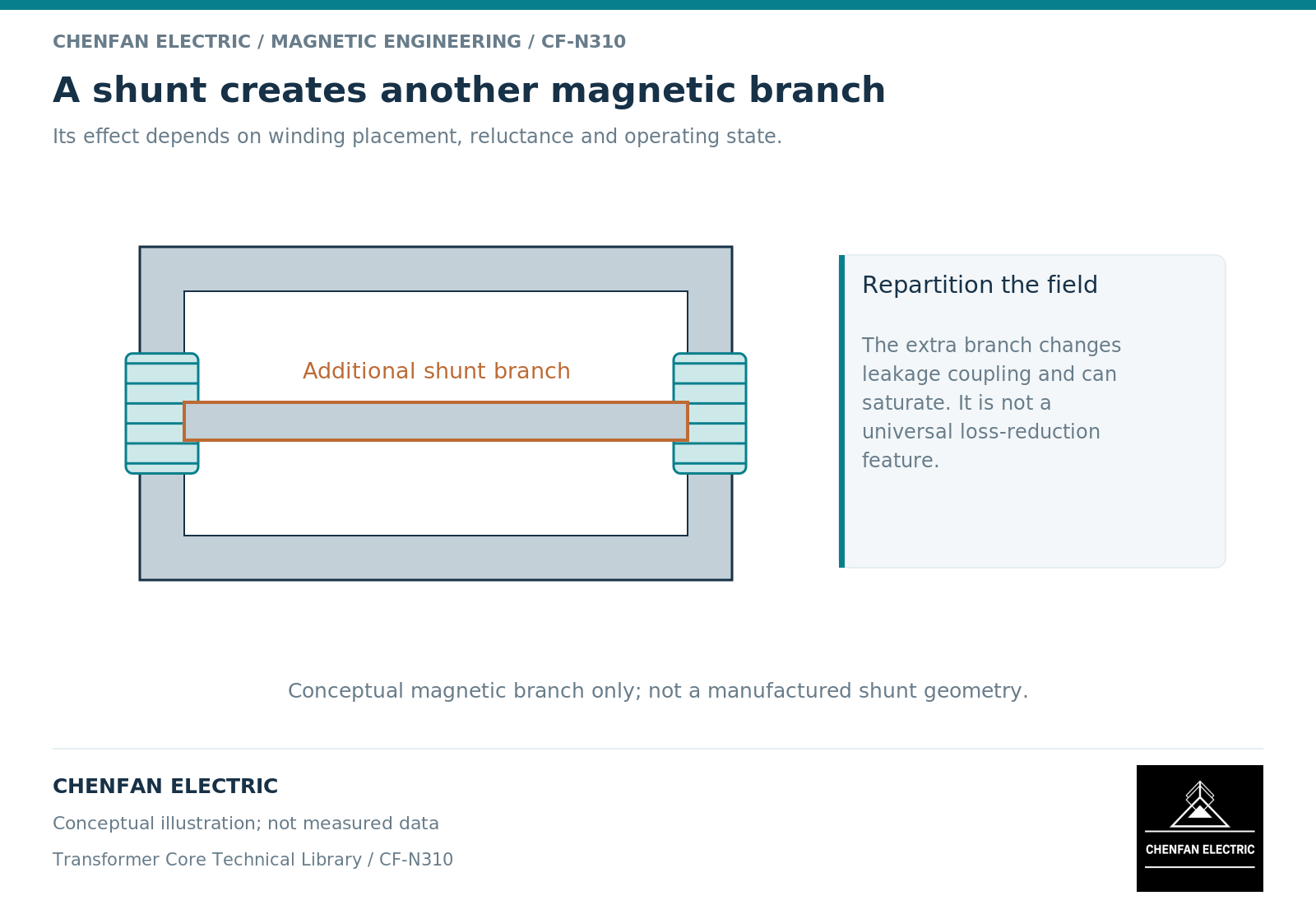
The principal core flux links the transformer windings according to their arrangement. Leakage flux does not link all windings equally and contributes to the leakage behavior represented in the equivalent circuit. A shunt can provide an additional magnetic route that changes this relationship. The words “extra steel” do not establish whether the shunt carries useful main flux, controlled leakage flux or unwanted stray flux. [1]
Start with a diagram showing the windings, the main core and the proposed shunt. Mark the intended flux route and the regions whose coupling changes. This is particularly important in special-purpose transformers where a deliberately modified current-voltage characteristic may be part of the application.
A shunt used to shape coupling should also be distinguished from a magnetic shield used primarily to reduce field exposure of a structural part. Similar materials can serve different design objectives, and the acceptance evidence should follow the objective.
Translate the objective into a response quantity
A useful requirement identifies what the shunt is meant to change: leakage inductance, current limitation, coupling, local field distribution or another specified response. It should state the operating range, not only a single nominal point. If saturation is intentional, the nonlinear characteristic is part of the design rather than a condition to be ignored.
A linear equivalent circuit can be useful for an initial comparison. It may not describe a shunt whose permeability changes substantially during the operating cycle. In that case, the relationship between voltage, current and flux must be checked over the relevant excitation range. A material law and field representation appropriate to the question are necessary. [2]
Do not assume that increasing shunt area always increases the desired effect. The result also depends on path length, gap geometry, location relative to the windings and the reluctance of competing routes. Changes can redistribute field rather than simply reduce it everywhere.
Examine the consequences outside the target circuit
The shunt itself can dissipate loss and transfer heat to nearby insulation. Its placement can alter fields in clamps, leads or the tank. Magnetic forces can act on its supports. These effects belong to the active-part review even when the shunt’s nominal electrical objective is achieved.
A local field reduction at one point is therefore not a complete success criterion. Compare the relevant response over the surrounding region and include integrated loss where heating is the concern. A finite-element color plot should retain the same scale across candidates and should not conceal a new concentration just outside the original observation area.
Similarly, a measured terminal impedance does not uniquely reveal the internal field distribution. It can support the overall electrical characteristic without proving that every structural component remains thermally acceptable.
A shunt review card
| Review item | Required definition |
|---|---|
| Intended function | The electrical or field response being changed |
| Magnetic connection | Main path, leakage route, gaps and adjacent branches |
| Operating envelope | Voltage, current, frequency, waveform and duration |
| Material basis | Directional and nonlinear properties where relevant |
| Consequence checks | Shunt loss, nearby heating, insulation and support forces |
For a hypothetical comparison, hold the winding geometry and operating waveform constant while changing one shunt dimension. Compare both the target inductive response and the loss in nearby structures. If the electrical target improves but structural loss increases, the result is a trade-off requiring further design work, not an unqualified improvement.
The handover to a core manufacturer should state whether the shunt is part of the supplied magnetic assembly and which dimensions or materials are controlled. Educational discussion of such arrangements does not establish a supplier’s capability to manufacture every special transformer. The engineering conclusion remains specific: a shunt is acceptable when its intended function and its active-part consequences are both supported for the defined duty.
References
[1] Lloyd Dixon / Texas Instruments. Magnetics Design 1 – Introduction and Basic Magnetics.
[2] David Meeker. Finite Element Method Magnetics User Manual.