

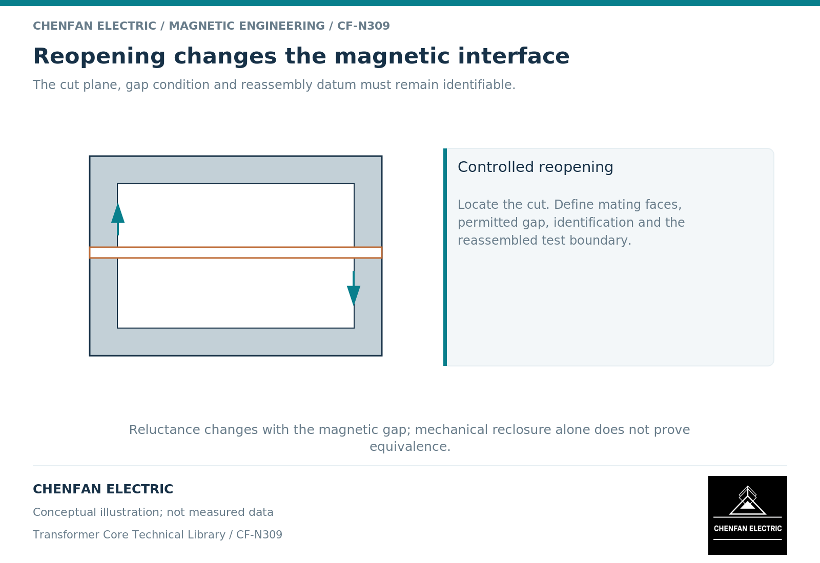
A split core or cut core must be specified by what needs to open, how it is reassembled and what magnetic interface is expected afterward. A joint introduced for assembly is not automatically an intentional energy-storage gap. Treating those two features as equivalent can lead to the wrong excitation, inductance and acceptance requirements.
Define the reason for opening
Some assemblies need a removable portion so that preformed windings can be installed. Others need repeated opening during service or inspection. A cut tape-wound core may use matched mating faces, while a laminated assembly may use a controlled packet or joint sequence. These constructions should not be grouped under one vague instruction to supply an “openable core.”
Specify whether opening occurs once during manufacturing or is part of the expected service life. Identify which parts remain matched, how their orientation is controlled and which party restores the final assembly. The magnetic evidence must correspond to that delivered and reassembled condition.
A pre-dispatch test on a closed core does not automatically establish the result after it is opened, handled and rebuilt elsewhere. The handover must say whether reassembly is included in the tested configuration or remains a later responsibility.
Distinguish a joint from a designed gap
A deliberate gap is introduced to obtain a magnetic characteristic, often to support stored-energy duty in an inductor or reactor. A reopening joint may instead be intended to restore a low-reluctance path as closely as the construction permits. Both can contain nonmagnetic space, but their engineering objectives differ. [1]
A simple linear screening relation is Rg = g/(mu0 A), where Rg is gap reluctance, g is gap length, A is the effective area and mu0 is free-space permeability. Fringing changes the effective area, and the rest of the circuit contributes its own reluctance. The equation shows why an apparently small separation can matter; it does not provide a universal joint tolerance.
For a conceptual example with g = 0.0001 metre and A = 0.010 square metre, the idealized gap reluctance is approximately 7,958 ampere-turns per weber. The value assumes a uniform field and excludes fringing. It is an illustration of sensitivity, not an allowable assembly gap.
Specify evidence at the restored interface
The relevant inspection and test scope depends on the construction. A matched cut-face arrangement may require identification of mating halves and their orientation. A removable laminated yoke may require a controlled reassembly sequence and a final magnetic check. A joint with a designed spacer requires that spacer to remain part of the magnetic definition.
Avoid borrowing a generic step-lap acceptance statement for a different cut-core interface. The contact geometry, flux direction and reopening process may not be comparable. A field model that represents the joint as an ideal continuous material also cannot be used to demonstrate the effect of an unmodeled separation. Numerical material and boundary choices determine what the model can answer. [2]
Use a reopening requirements schedule
| Requirement | What the order should identify |
|---|---|
| Opening purpose | Winding installation, service access or another defined operation |
| Matched parts | Identification, orientation and interchangeability restrictions |
| Magnetic intent | Low-reluctance restored joint or deliberate specified gap |
| Final condition | Who completes reassembly and which state is tested |
| Evidence boundary | Dimensional, magnetic and insulation records that apply afterward |
Keep mechanical restraint and electrical insulation in the same interface review. A joint can be magnetically acceptable while a reassembly change introduces an unintended conductive contact. Conversely, a mechanically tight joint does not by itself prove the contracted magnetic performance.
The practical result is a controlled reopening and restoration definition. It allows the core supplier and transformer assembler to compare the same product state, rather than discovering after delivery that one party priced matched components while the other expected a fully qualified repeatedly openable assembly.
References
[1] Lloyd Dixon / Texas Instruments. Magnetics Design 5 – Inductor and Flyback Transformer Design.
[2] David Meeker. Finite Element Method Magnetics User Manual.