

A toroidal core offers a closed magnetic path, but that advantage comes with a winding and assembly constraint: conductors must be arranged around a closed ring. At utility frequency, topology selection should consider insulation, conductor size, manufacturing access and repair strategy as well as excitation and stray-field behavior. A toroid is not an automatic upgrade for every transformer rating.
Understand the attractive magnetic feature
A continuous ring avoids the same type of corner and removable-yoke geometry found in many laminated frame cores. In an ideal uniformly wound toroid, the magnetic field is concentrated around the ring and the main path has rotational symmetry. The familiar approximation H = NI/l relates magnetic field strength H to turns N, current I and mean path length l. [1]
Real windings are not perfectly uniform. Lead exits, insulation gaps and uneven conductor distribution disturb the idealized arrangement. The inner and outer portions of the core also have different path lengths. A single mean-path calculation is useful for screening, but it does not prove that the local field or temperature is uniform throughout the assembly.
Nor does a closed path eliminate inrush. Residual magnetic state, applied voltage integral, circuit impedance and switching conditions still affect energization. Low excitation in steady operation should not be described as evidence of low transient current.
Treat winding access as part of the topology
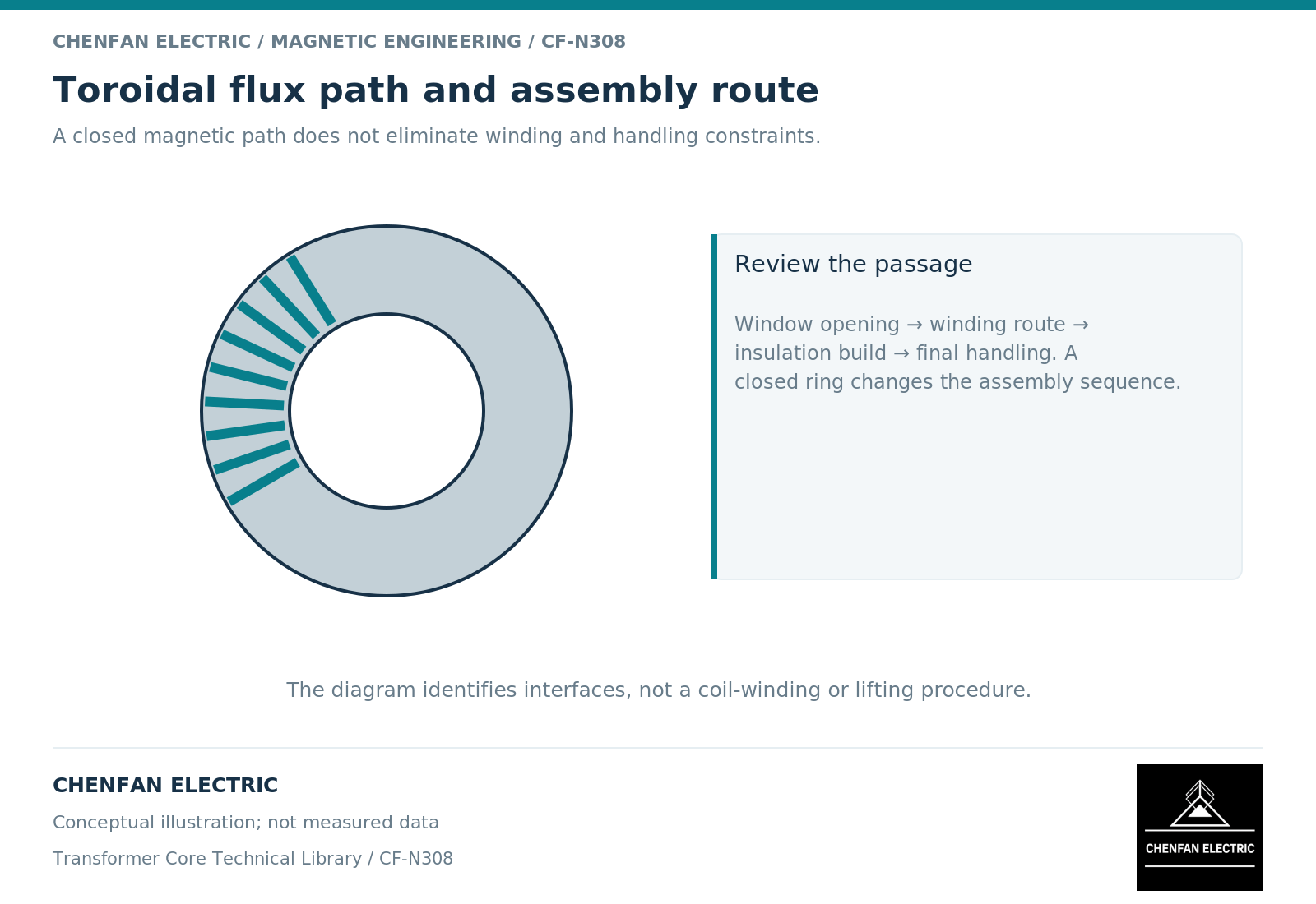
A closed ring changes how the winding is produced. Conductor must pass through or be placed around the central opening using a process compatible with its size, insulation and turn count. As layers accumulate, the remaining opening and access change. This is a manufacturing constraint inherent to the geometry, not merely a choice of winding machine.
Transformer-design guidance identifies winding difficulty as an important limitation of toroidal arrangements. Its specific discussion concerns switch-mode equipment, so utility-frequency selection still requires a rating-specific process review rather than importing its manufacturing conclusions wholesale. [2]
The same access question appears during repair. A design that is efficient to manufacture as a complete unit may not support the disassembly sequence expected for a large repairable active part. A cut or split ring changes the magnetic and mechanical boundary and should be treated as a different construction.
Do not overlook the electrical interfaces
The core, primary winding, secondary winding and external mounting arrangement need a coordinated insulation system. A low external magnetic field does not establish dielectric performance. Lead routing, creepage and clearance requirements, mechanical support and thermal paths remain part of the transformer design.
Mounting details deserve particular attention because conductive hardware can create unintended current paths if its arrangement links changing flux. This is a design-review issue for the complete assembly, not permission to alter mounting or grounding hardware in the field. The reviewed mechanical arrangement should preserve both electrical insulation and the intended absence of harmful conducting loops.
Cooling also depends on where losses occur and how heat leaves the windings and core. Surface area and enclosure conditions matter; neither a toroidal outline nor a low material-loss figure supplies a complete temperature-rise result.
A selection gate for an OEM review
Before comparing toroidal and frame-core candidates, answer four questions with identified evidence. Can the required conductors and insulation be wound without compromising the design? Does the assembly meet the electrical and thermal duty? Is its mounting arrangement compatible with the magnetic field? Can the required service and replacement strategy be carried out?
A useful comparison record keeps the following claims separate: calculated excitation, measured complete-transformer loss, assessed insulation performance and demonstrated manufacturing feasibility. Evidence for one should not be relabeled as evidence for all four.
If the application requires a removable core section, large formed windings or a particular active-part assembly sequence, those requirements may dominate the choice. Where a closed-ring winding process and the electrical duty are compatible, the toroidal option can be evaluated on its merits. The decision should come from that complete comparison, not from the general statement that a closed magnetic path is better.
References
[1] Lloyd Dixon / Texas Instruments. Magnetics Design 1 – Introduction and Basic Magnetics.
[2] Lloyd Dixon / Texas Instruments. Magnetics Design 4 – Power Transformer Design.