

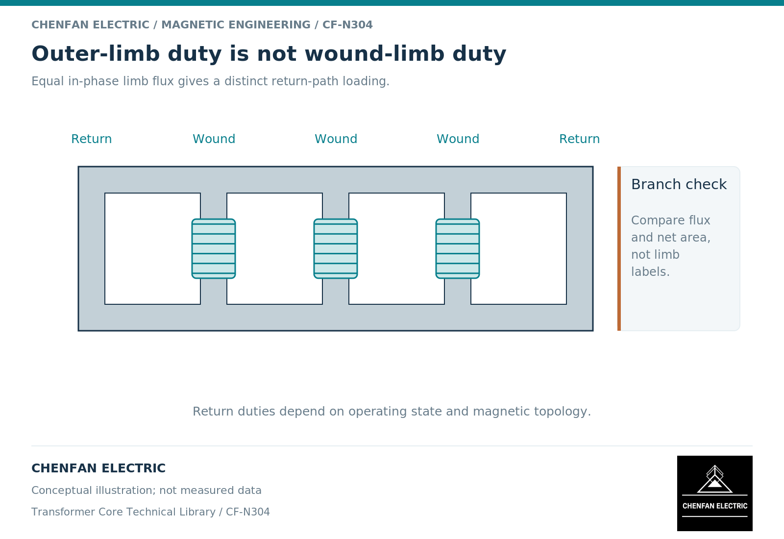
Outer limbs in a five-limb transformer core are return branches, not interchangeable copies of the three wound limbs. Their flux depends on the complete magnetic network and on the excitation case. Their cross-sections should therefore follow a branch-duty assessment rather than a fixed percentage copied from another design.
Identify what each branch must carry
The wound limbs link the principal phase windings. The outer limbs provide additional return routes through the upper and lower yokes. During balanced operation, flux sharing depends on the geometry and reluctance of the available paths. During zero-sequence excitation, the outer return network can carry a common-mode component that does not cancel among the three wound limbs.
The yokes connect these duties. A return limb cannot be reviewed in isolation from the yoke sections feeding it. A generous outer-limb area does not remove a constriction in the connecting yoke, and a low average density in a wound limb does not prove that every return segment has adequate margin. Geometry-based magnetic models distinguish winding-limb, yoke and outer-limb proportions for this reason. [1]
Use net area and branch flux together
For a specified section, the average flux density is B = Phi/A, where Phi is the flux through that section and A is its net magnetic area. The relationship is simple, but the difficult input is often the branch flux. Assigning the wound-limb flux to every outer limb, or assigning an assumed half-flux without solving the network, can both be wrong.
In a linear conceptual network, reluctance is proportional to magnetic path length and inversely proportional to permeability and area. When a return branch approaches saturation, its incremental permeability changes, so the flux sharing and required magnetomotive force change as well. A single constant-reluctance solution may no longer describe the limiting case. [1] [2]
Net area must also mean the same thing throughout the calculation. Cooling passages and nonmagnetic spaces do not carry flux as steel does. An envelope dimension is not a substitute for the magnetic area used by the designer.
Illustrative common-mode comparison
Suppose three wound limbs each carry an illustrative zero-sequence flux component of 0.003 weber in the same direction. Their combined component is 0.009 weber. If a deliberately simplified symmetric return network assigns all of that component equally to two outer limbs, each carries 0.0045 weber.
At a net return area of 0.003 square metre, the corresponding average component is 1.50 tesla. This is not necessarily the total instantaneous density: any other flux component in the same branch must be combined with the correct time relationship. Nor does the example establish that all return flux stays in the outer steel in an actual transformer.
The calculation is useful because it exposes two assumptions that often disappear in a dimension schedule: equal return sharing and the exclusion of other paths. Both must be supported before the result becomes a design input.
Release a duty map, not a universal ratio
For each outer limb and adjoining yoke segment, record the normal-duty envelope, the specified unbalanced cases, the associated duration and the source of the calculated flux. Where a nonlinear field or magnetic-circuit model is used, retain the material basis and the electrical winding states.
| Branch check | Evidence needed |
|---|---|
| Normal flux sharing | Balanced-case branch results and geometry revision |
| Common-mode return | Defined zero-sequence excitation and connection state |
| Limiting section | Local net area and combined peak flux basis |
| Thermal consequence | Loss distribution and the relevant cooling boundary |
The manufacturing drawing should preserve the approved outer-limb and yoke dimensions, including changes that appear mechanically minor but alter magnetic area. Any proposed reduction needs an electromagnetic review, not only a steel-weight recalculation.
A credible outer-limb design is therefore case-dependent. Its purpose is to close the required magnetic paths without transferring an unexamined saturation or heating problem into another branch of the active part.
References
[1] Manitoba Hydro International / PSCAD. The UMEC Approach.
[2] Lloyd Dixon / Texas Instruments. Magnetics Design 1 – Introduction and Basic Magnetics.