

Rated voltage does not establish rated flux when the frequency is wrong.
For a fixed winding and core area, the excitation condition depends on voltage per turn relative to frequency, not on voltage alone.
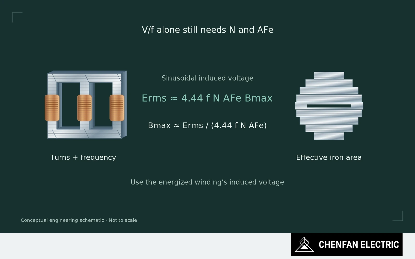
Use the voltage equation within its assumptions
Under sinusoidal conditions, the induced RMS voltage is approximately 4.44 f N A Bmax. Here A is effective iron area and the voltage is associated with the energized winding. Terminal voltage is a useful approximation only where the relevant voltage drops and waveform effects are appropriately accounted for.
Increasing V/f therefore raises the flux excursion when turns and area are unchanged. As the core moves toward a steep region of its magnetization characteristic, the required exciting current can rise sharply. Loss and acoustic behaviour can also change, but not by one universal multiplier.
The local picture may differ from the section average. Joint regions and other non-uniform flux paths can experience conditions that a single average B value does not describe. A design margin based only on nominal limb flux density can therefore miss the location that controls the response.
Distinguish local saturation and energization inrush
Check the actual cause of an apparent over-flux condition. Frequency, the energized tap, winding connection, effective area and the interpretation of voltage all matter. A distorted waveform also requires more care than inserting an RMS reading into the sinusoidal equation.
Do not confuse sustained over-fluxing with every transient high-current event. Energization inrush involves switching conditions and residual flux; it is not diagnosed from the same steady-state current limit alone.
For testing, increased excitation must stay within the approved procedure and equipment capability. A percentage used on another design is not a safe operating allowance for this one. The specified duration and thermal or electrical limits belong to the assessment.
Verify the actual operating and approved test conditions
For procurement, request material and finished-core evidence over the operating region that the transformer design actually needs. A favourable loss point well below that region does not establish behaviour near the intended upper excitation condition.
There is no universal flux-density number that makes all GOES cores acceptable or unacceptable. The relevant limit comes from the complete design, service conditions and verified response.
Before blaming a core for high current, establish the volts per turn, frequency and area it was actually asked to work with. The nameplate voltage alone cannot answer that question.
Practical takeaway
Rated terminal voltage can still produce an unintended flux level when frequency or the winding basis differs.
Chenfan Electric manufactures custom transformer cores according to customer drawings. Where applicable to the specified material and core design, agreed process controls include burr height below 0.02 mm and stacking factor above 97%. Measurement methods and acceptance conditions are defined for each order.