

Most of the steel follows a relatively orderly path.
The joint has to redirect and transfer the flux.
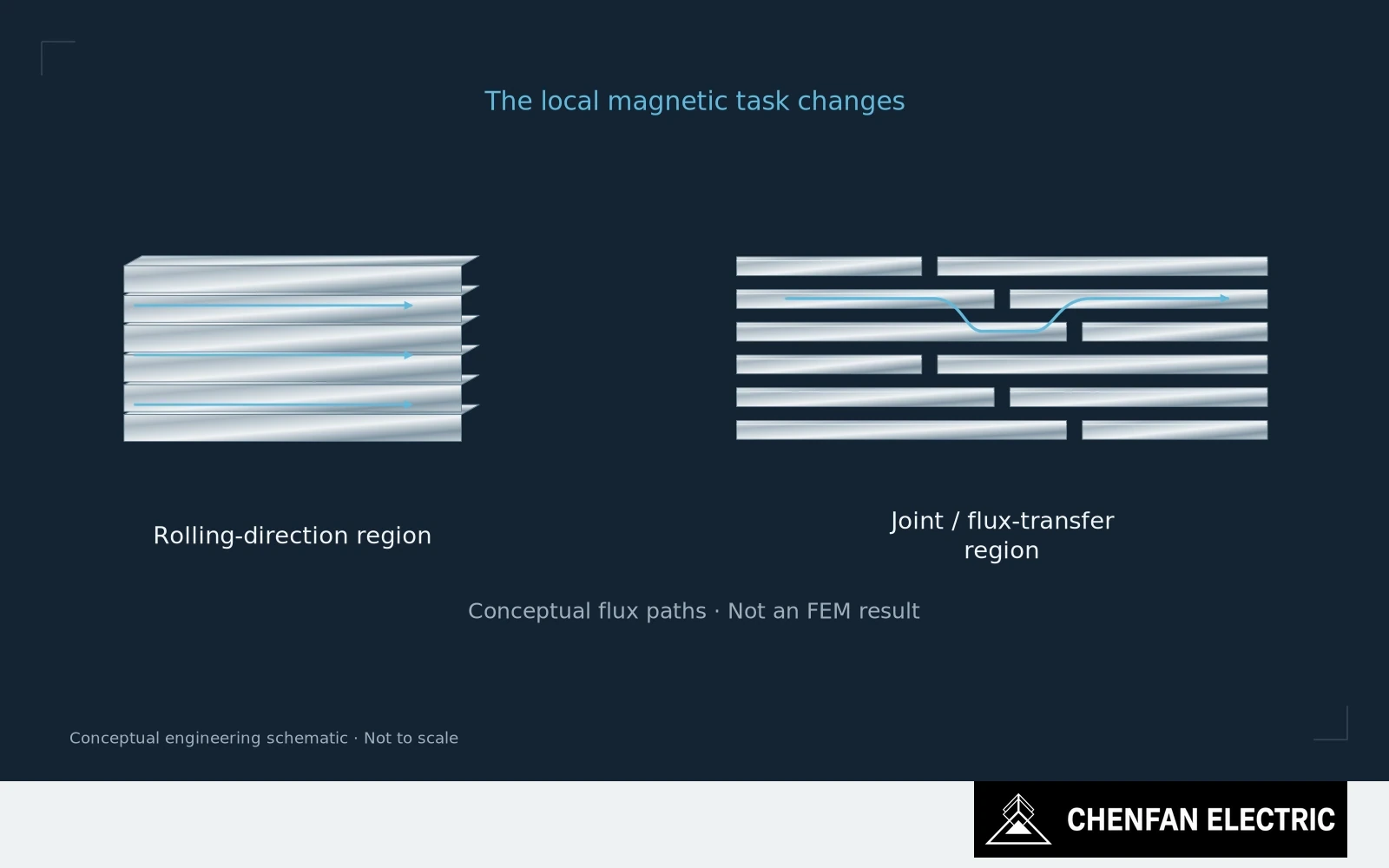
Understand the joint’s flux-transfer task
That difference is why joint engineering deserves attention out of proportion to the joint’s share of total core mass.
In a straight, well-oriented section, the design aims to use GOES along its favorable rolling direction. Near a joint, the local field must accommodate the change in geometry and the interruptions between laminations. Flux distribution becomes less uniform than the nominal limb induction suggests.
Step-lap geometry provides a controlled way to distribute those transitions. It does not make the joint disappear magnetically. Overlap, gap, layer sequence and packet arrangement still influence how the transfer occurs.
Compare local conditions with the design assumption
Some local flux components can depart from the preferred in-plane direction or cross between layers. These conditions are not represented by taking a rolling-direction material loss value and assigning it uniformly to the whole joint volume.
This matters when an engineer tries to diagnose a core using only the average induction. A satisfactory average does not establish that every local region has the same margin from saturation. Equally, the presence of a joint does not establish that it is defective; the design deliberately accommodates a nonuniform field there.
The right question is whether the as-built transition matches the one the design and loss estimate assumed.
Review the joint as a repeating geometry, not as a photograph of one attractive corner. Check the relationship between consecutive layers, the packet boundaries and the alignment of the adjoining sections. A small error repeated through the intended sequence is a different problem from one isolated misplaced sheet.
Verify repeating geometry, not one attractive corner
For development work, local measurements or a validated field model can help identify where the nominal description is inadequate. Their resolution and assumptions should be stated. A colorful field plot is not evidence unless its material model, geometry and boundary conditions represent the actual assembly.
Procurement does not need to prescribe every internal modeling detail. It does need a supplier that can maintain the agreed joint recipe and identify when a proposed manufacturing change alters it.
The joint is where the magnetic path becomes an assembly problem. Treating it as leftover steel at the corner is a poor basis for either design review or supplier qualification.
Practical takeaway
The joint has a flux-transfer task that a straight limb does not.
Chenfan Electric manufactures custom transformer cores according to customer drawings. Where applicable to the specified material and core design, agreed process controls include burr height below 0.02 mm and stacking factor above 97%. Measurement methods and acceptance conditions are defined for each order.