

One excitation point gives you a result.
Several agreed points give you the beginning of a response curve.
Define the reference behind each percentage
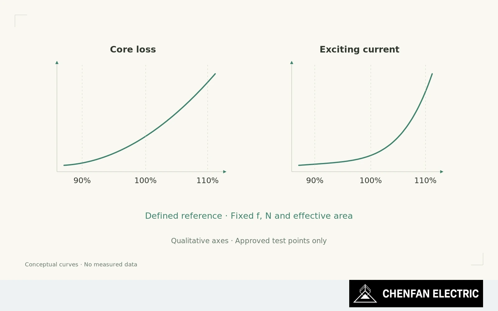
For a suitable core-development test, 90%, 100% and 110% of a defined reference excitation can be a useful example. They are not a universal instruction to test every core at those levels, nor proof that every transformer must meet the same limits there.
Define what the percentage means. With unchanged turns, effective area and frequency, and an appropriate voltage waveform, voltage scaling can approximately scale peak flux density. If frequency or the flux-reference method changes, “110% voltage” no longer describes a comparable magnetic condition by itself.
At the lower point, the measurement can establish a baseline away from the upper operating region. At the reference point, it addresses the intended performance allocation. At the higher point, it can show how rapidly loss and exciting current rise as parts of the magnetic circuit become more nonlinear.
Interpret the shape of loss and current curves
The value lies in the change of shape. Two cores that are close at the reference point may separate at a higher permitted excitation. That observation warrants investigation of material curves, joint geometry, stress and the actual test conditions. It does not identify one of them as the cause automatically.
Current deserves its own curve. Scaling its reference-point value in direct proportion to voltage is not reliable near magnetic saturation. Likewise, a fixed power-law estimate for loss should not replace measurement across a range where the material and joint response may change.
Keep the sequence and mechanical state consistent. Record whether the readings were taken on an increasing or decreasing excitation sequence, and apply any magnetic preparation required by the agreed method. Changing the clamp or test winding between points defeats the intended comparison.
Keep additional test points within approved limits
The test plan must also define equipment capability, duration and stop conditions. A diagnostic excursion should remain within the approved design and test limits. More excitation is not automatically more information if it changes the specimen or exceeds a safe operating condition.
For procurement, ask for extra points only when they answer a design or qualification question. Specify the reference, quantities and interpretation before the test. Otherwise the supplier may deliver three numbers that still cannot be compared.
The curve is a tool for understanding sensitivity. It becomes an acceptance test only where the contract and applicable procedure explicitly make it one.
Practical takeaway
Three defined points can reveal response shape, but they are not a universal compliance requirement.
Chenfan Electric manufactures custom transformer cores according to customer drawings. Where applicable to the specified material and core design, agreed process controls include burr height below 0.02 mm and stacking factor above 97%. Measurement methods and acceptance conditions are defined for each order.