

A weld repaired several times has a changing excavation and thermal history. The final surface may conceal how much material was removed and which region experienced repeated heating. A location map keeps that history tied to the remaining oil-retaining structure. [1]
Use weld ID, position along the seam and a local cross-section reference. Record each original indication, excavation extent and the material remaining before the next weld. Preserve earlier revisions rather than overwriting them with the final photograph.
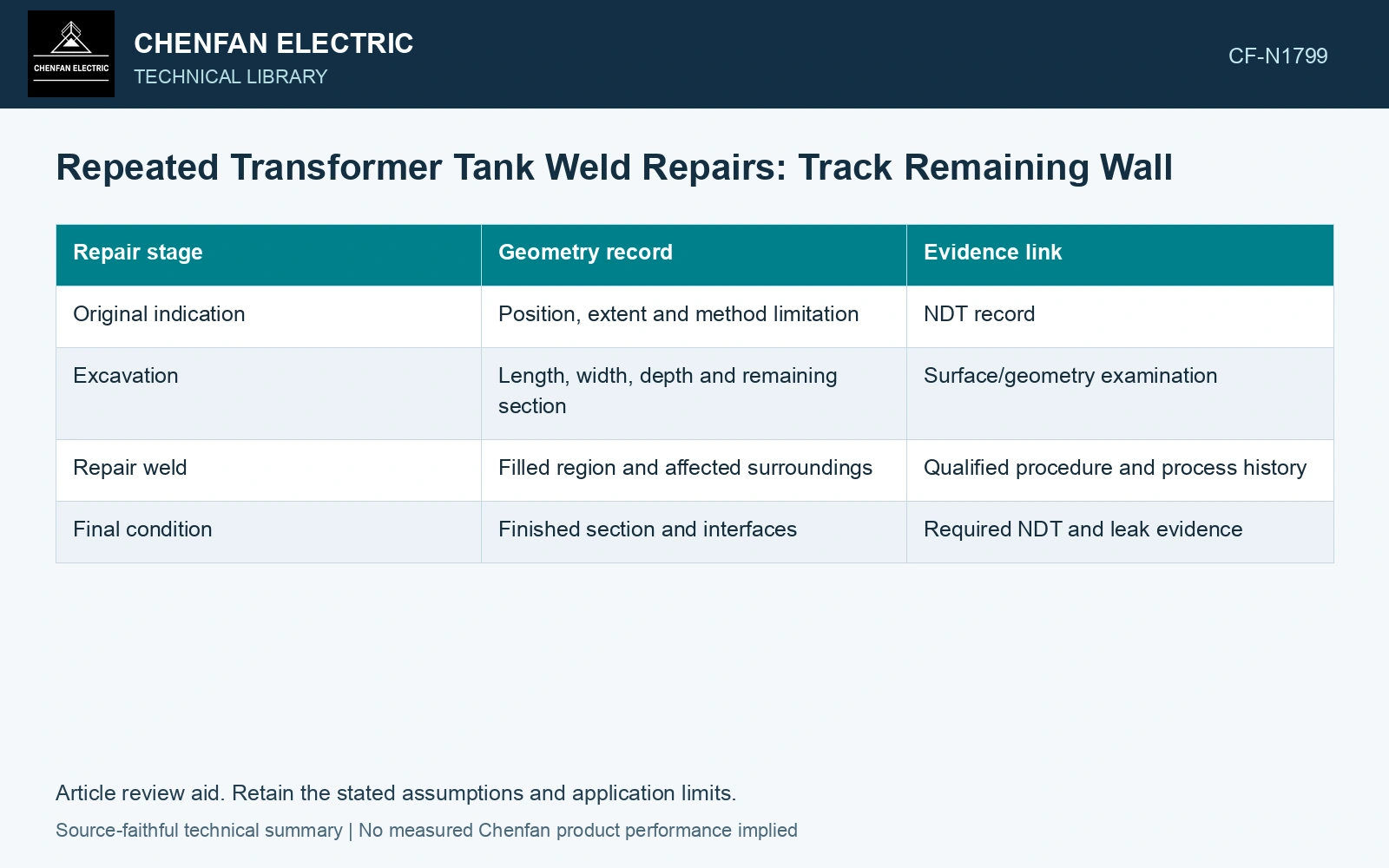
| Repair stage | Geometry record | Evidence link |
|---|---|---|
| Original indication | Position, extent and method limitation | NDT record |
| Excavation | Length, width, depth and remaining section | Surface/geometry examination |
| Repair weld | Filled region and affected surroundings | Qualified procedure and process history |
| Final condition | Finished section and interfaces | Required NDT and leak evidence |
Check removal as well as deposition
Removing an indication may also reduce adjacent parent metal or change the joint preparation. The next weld must fit the qualified repair basis. A final bead profile cannot recover an undocumented remaining-wall dimension.
Repeated thermal cycles can affect the material and distortion, depending on steel, process and restraint. Evaluate them through the applicable qualified basis rather than imposing a universal maximum repair count.
Choose NDT using material, weld thickness, welding process, quality requirements and demonstrated coverage. NDT acceptance levels are not a detailed one-to-one translation of weld quality levels. [2]
Track excavation against remaining thickness
Assumptions: an initially verified 6.0 mm parent wall experiences removals of 0.8 and 0.7 mm at the same controlling location; no restored deposit is counted in this parent-metal screen. Remaining parent thickness is 6.0 − 0.8 − 0.7 = 4.5 mm. Against an assumed repair-design minimum of 5.0 mm, the 0.5 mm shortfall prevents release on that screen. Resolve the section through the approved repair design and deposited-metal qualification before another grind. If intervening deposition changes the load-carrying section, reconstruct that actual cross-section rather than subtracting excavation depths from unrelated stages.
References
- U.S. Federal Highway Administration, Bridge Welding Reference Manual, FHWA-HIF-19-088, 2019.
- ISO, ISO 17635:2025, Non-destructive testing of welds — General rules for metallic materials.