

A duct bank with several spare holes can look lightly loaded while its central occupied cable becomes the thermal bottleneck. Heat must cross the cable-to-duct interface, the duct wall and the surrounding bank and soil. Neighboring loaded positions add heat along the same paths. [1]
A cable ampacity table is only useful when its installation assumptions match those conditions. The assessment should start with a position map rather than the total number of ducts.
Distinguish four occupancy states
An empty duct, an installed unenergized cable, an energized circuit and a reserved future circuit are different states. An unenergized cable does not generate the same load losses, but it still changes the physical contents of the duct. It can also have induced metallic-layer losses where coupled fields and a closed conductive path permit them; account for that electrical boundary rather than automatically setting every loss to zero. A future circuit needs a separate scenario if it is expected to operate while the existing feeder remains loaded.
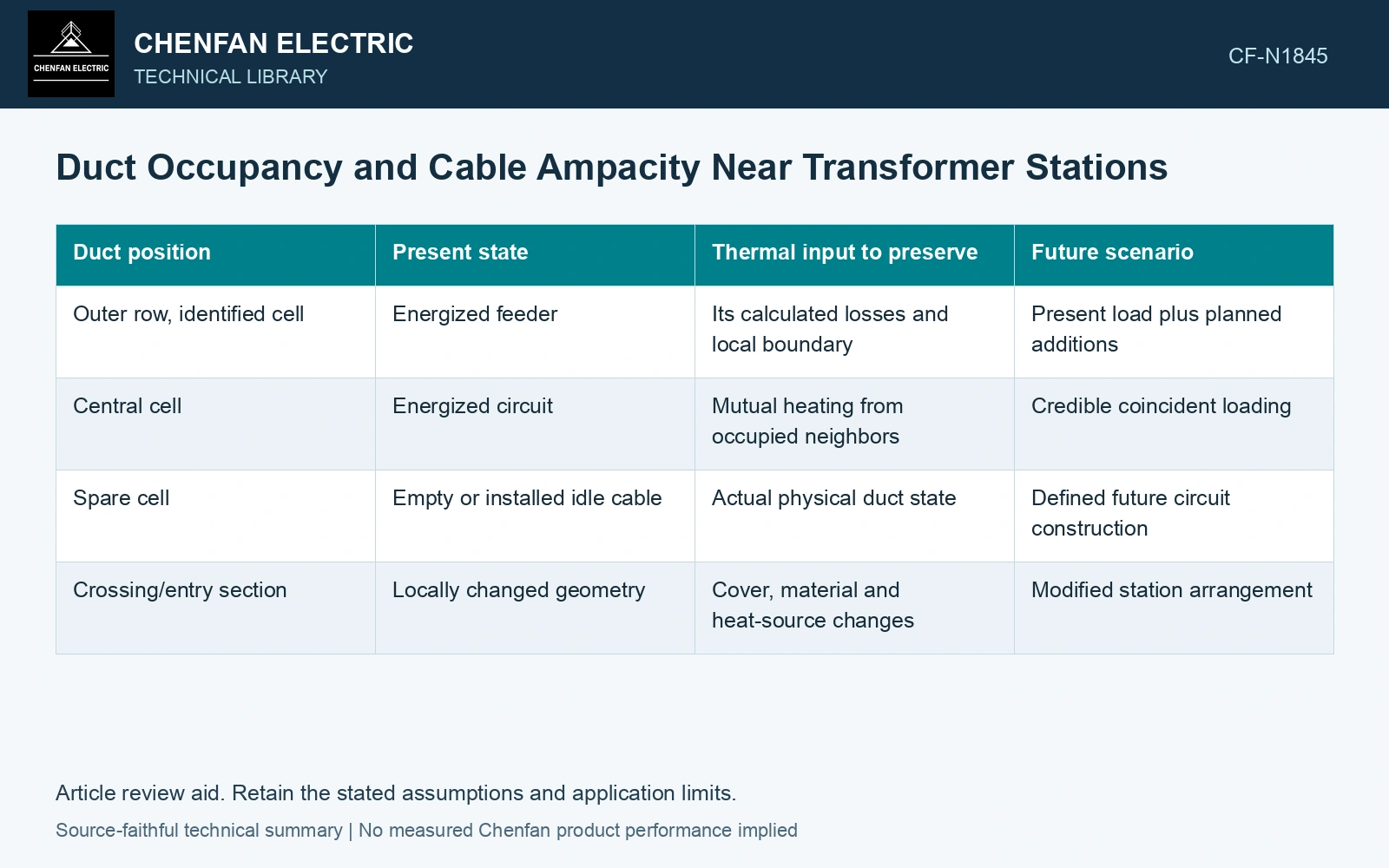
| Duct position | Present state | Thermal input to preserve | Future scenario |
|---|---|---|---|
| Outer row, identified cell | Energized feeder | Its calculated losses and local boundary | Present load plus planned additions |
| Central cell | Energized circuit | Mutual heating from occupied neighbors | Credible coincident loading |
| Spare cell | Empty or installed idle cable | Actual physical duct state | Defined future circuit construction |
| Crossing/entry section | Locally changed geometry | Cover, material and heat-source changes | Modified station arrangement |
Attach actual cell identities to the matrix. Terms such as two spares are insufficient if moving those spares to another row changes the limiting cable’s surroundings.
Preserve the thermal interfaces
The cable inside a duct has a different external heat path from a directly buried cable. Air space, contact, duct material and any approved fill arrangement belong in the model. Do not select a favorable interface property because it makes a catalog rating fit.
The bank itself needs installed dimensions and material properties. Concrete or another surrounding material can be represented only with a justified property and geometry. Native soil remains part of the external thermal path, including its moisture and seasonal uncertainty.
Compare positions before summing capacity
Calculate the temperature of each loaded circuit using the applicable losses and mutual heating. The central position may govern, but a local boundary or crossing can make another position worse. The result should identify the limiting position and route section.
For a linear thermal network, each cable temperature receives self-heating and mutual-heating contributions from the occupied positions. Preserve those individual paths rather than averaging the total number of loaded ducts. [2]
Evaluate mutual heating by position
Assumptions: a limiting cable has 35 K self-heating plus 8 K from each of two loaded neighboring ducts, at 35 °C ambient. The conductor acceptance gate is 85 °C. With both neighbors loaded, its temperature is 35 + 35 + 8 + 8 = 86 °C and fails by 1 K. With one neighbor unloaded and its induced losses neglected in this example, temperature is 78 °C and passes with 7 K margin. Do not energize the future neighboring circuit at the assumed coincident load without reducing duty or improving the thermal path. The physical spare-duct map therefore belongs in the rating approval. [1][2]
References
- IEC, IEC 60287-1-1:2023, Electric cables — Calculation of the current rating — Part 1-1: Current rating equations (100 % load factor) and calculation of losses — General.
- U.S. Department of Energy, DOE-HDBK-1012/2-92, Thermodynamics, Heat Transfer, and Fluid Flow, Volume 2, 1992.