

A standby cooler may contain trapped gas at a high point even when oil appears at a lower connection. On changeover, flow can move that gas toward the transformer. The standby branch needs a verified filled state and a defined venting boundary. [1]
Draw the branch with its installed elevations, valves, vents, check valves and connection to the main oil loop. Identify pockets that cannot discharge through the intended vent path. A shop drawing without pipe elevation may miss the installed high point.
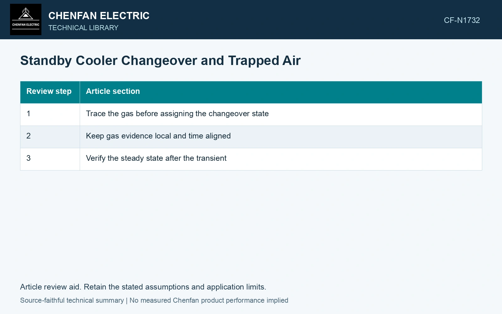
Trace the gas before assigning the changeover state
Identify where gas can accumulate during standby, maintenance or cooling.
Check whether each pocket has an approved filling and venting path.
Establish the branch condition that the plant procedure requires before connection.
Follow the first flow path after valves change state, including the route toward the active part.
Compare gas-monitoring indications with that route and event timing.
This is a review sequence. Actual filling, venting and valve operations must follow the cooler and transformer procedures; the list supplies no pressure, timing or bypass instruction.
Keep gas evidence local and time aligned
An indication after changeover may originate in the standby branch, another maintenance boundary or the transformer itself. Retain valve times, pump state and gas observations. A visible vent discharge does not alone prove every internal pocket is empty.
Oil temperature changes can affect dissolved-gas behavior and physical volume, further complicating interpretation. Do not equate every bubble with an active internal electrical fault, or dismiss every gas indication as harmless changeover air.
For a released gas packet, distinguish its initial pocket from the downstream transport path. Continuity can estimate a liquid displacement time; a two-phase pocket with buoyancy, slip or recirculation needs a different transport model. [2]
Separate pocket release from downstream transit
Assume a released gas packet is carried without slip through a 25 L liquid-filled connecting path at steady 10 L/s. The ideal displacement time is 25/10 = 2.5 s. A sensor event around that time is compatible with the assumed route; it cannot prove the origin or removal of an unreleased pocket. Map high points and confirm the filled/vented state before accepting standby changeover readiness.
References
- U.S. Bureau of Reclamation, FIST Volume 3-30, Transformer Maintenance, 2000.
- U.S. Department of Energy, DOE-HDBK-1012/3-92, Thermodynamics, Heat Transfer, and Fluid Flow, Volume 3, 1992.