

A conductor substitution can start with a persuasive calculation: increase the cross-section until the new material has the same winding resistance. The calculation answers one question. It does not establish an equivalent winding, because the larger section may no longer fit the same cooling, insulation and mechanical arrangement. [1]
Treat copper-to-aluminium and aluminium-to-copper changes as design changes during a rewind. The original material may have been chosen for reasons that are absent from the surviving drawings. A repair estimate should preserve that uncertainty instead of treating equal resistance as a complete specification.
What equal resistance really assumes
For a uniform conductor, R = ρL/A. R is resistance in ohms, ρ is resistivity in ohm-metres, L is conductor length in metres and A is conducting area in square metres. Comparing two materials at the same defined temperature gives A2/A1 = ρ2L2/(ρ1L1) for equal resistance.
The length term matters. A changed cross-section can move the mean turn perimeter; keeping the turn count does not guarantee keeping L. The resistance calculation also excludes joint resistance and does not calculate additional AC losses. Use material-specific properties and the actual proposed geometry, rather than an unexplained conversion factor.
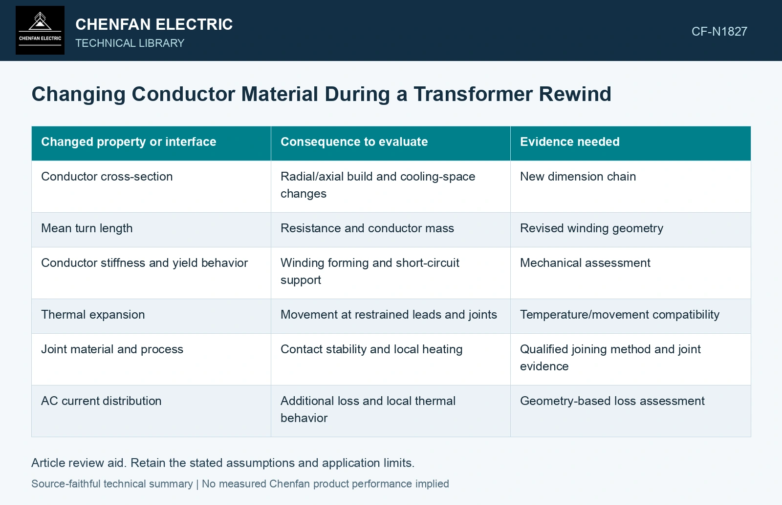
| Changed property or interface | Consequence to evaluate | Evidence needed |
|---|---|---|
| Conductor cross-section | Radial/axial build and cooling-space changes | New dimension chain |
| Mean turn length | Resistance and conductor mass | Revised winding geometry |
| Conductor stiffness and yield behavior | Winding forming and short-circuit support | Mechanical assessment |
| Thermal expansion | Movement at restrained leads and joints | Temperature/movement compatibility |
| Joint material and process | Contact stability and local heating | Qualified joining method and joint evidence |
| AC current distribution | Additional loss and local thermal behavior | Geometry-based loss assessment |
Follow the substitution through the lead exits
The new conductor may be acceptable within the coil and troublesome at the terminals. Different forming behavior can require a changed bend or support. A transition joint can create a new thermal and mechanical interface. Existing clamp hardware should not be assumed suitable merely because it can be tightened around the replacement lead.
Track every material transition from winding to terminal. Identify how contact pressure, surface condition and differential movement are controlled by the approved joint design. A low initial resistance measurement is evidence about that measured condition; it does not establish stability through all service cycles.
The equal-resistance check must preserve material resistivity, winding length and the actual terminal connection path at the same temperature. Conductor area is only one term in that electrical comparison. [2]
Calculate area before checking the window
Assumptions at the same 75 °C comparison temperature: replacement conductor resistivity is 1.60 times the original, mean conductor length is 1.02 times as long, and the original area is 100 mm². Equal resistance requires 100×1.60×1.02 = 163.2 mm². Suppose the approved window/duct/insulation envelope permits at most 150 mm² of this proposed conductor geometry. The equal-resistance option exceeds that envelope by 13.2 mm², or 8.8%. Using 150 mm² instead leaves resistance at 1.60×1.02×100/150 = 1.088 times the original, increasing I²R loss by 8.8% at unchanged current. Reject the proposed substitution as equivalent; redesign geometry, cooling and terminals before selecting either alternative. [2]
References
- U.S. Bureau of Reclamation, FIST Volume 3-31, Transformer Diagnostics, June 2003.
- U.S. Department of Energy, DOE-HDBK-1011/4-92, Electrical Science, Volume 4, 1992.