

Major repair changes the physical boundaries around a transformer core. A new clamp washer, damaged sleeve, retained temporary bond or metallic fragment can create a connection that was absent before dismantling. Verifying the intended core-ground arrangement therefore requires a map of paths, not just a check that one grounding strap is visible. [1]
Use the equipment’s approved grounding design as the reference. Core, clamp structure, tank and shields may have different intended electrical relationships. Do not combine them into one object called the core when assigning test boundaries. The investigation is performed on isolated equipment by qualified personnel.
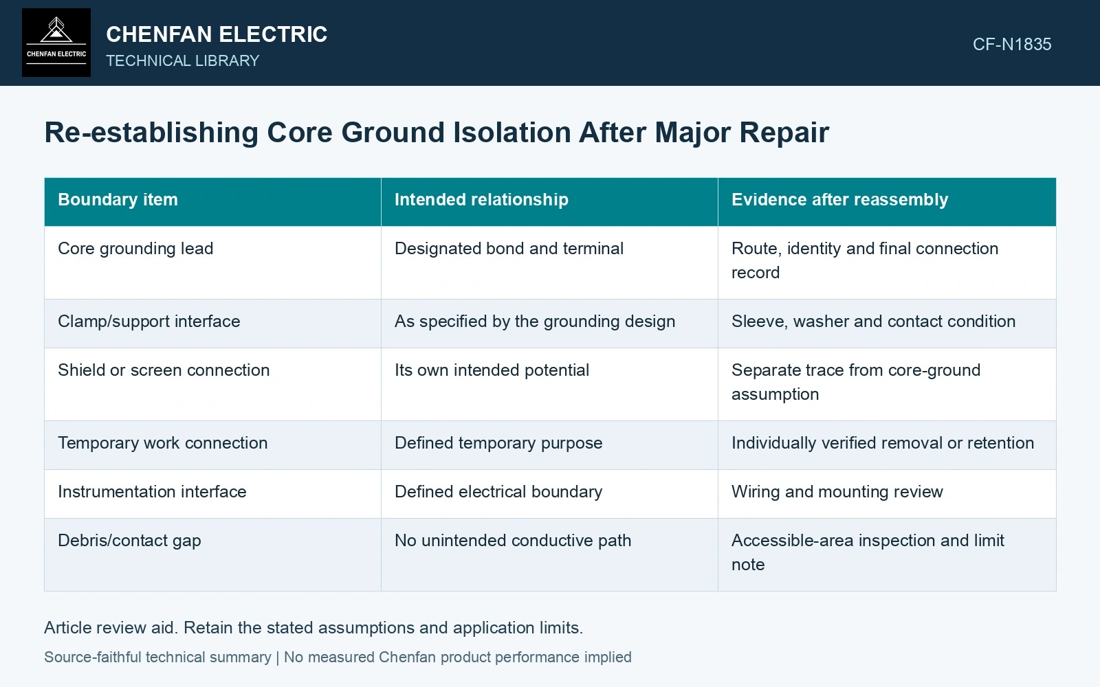
Map intentional and possible connections separately
Identify the designated bonds with component and drawing references. Then trace physical interfaces that could bypass the intended isolation: bolts through insulated members, clamp-to-tank supports, sleeves, washers, shields, instrumentation leads and debris at narrow gaps.
Temporary connections deserve individual identities. A bond fitted during work should have an installation purpose and a verified final state. A generic note saying temporary grounds removed cannot identify which circuit remains if the post-repair result is unexpected.
| Boundary item | Intended relationship | Evidence after reassembly |
|---|---|---|
| Core grounding lead | Designated bond and terminal | Route, identity and final connection record |
| Clamp/support interface | As specified by the grounding design | Sleeve, washer and contact condition |
| Shield or screen connection | Its own intended potential | Separate trace from core-ground assumption |
| Temporary work connection | Defined temporary purpose | Individually verified removal or retention |
| Instrumentation interface | Defined electrical boundary | Wiring and mounting review |
| Debris/contact gap | No unintended conductive path | Accessible-area inspection and limit note |
Choose test boundaries that answer the map
An insulation measurement is meaningful only for the boundary actually isolated and examined. Connected accessories or intentional bonds can dominate the reading. The approved test plan should identify what remains connected, what is isolated and what the result can say about the retained assembly.
A satisfactory bulk reading does not necessarily locate every intermittent mechanical contact. Conversely, an unexpected reading does not prove that the steel coating itself failed. Use the path map to narrow the question before assigning a cause.
Surface insulation resistance is a lamination-interface measurement; its defined specimen boundary does not establish assembled-core loss or every unintended metallic path. [2]
Resolve leakage isolation and a flux-linked metallic loop
FIST 3-31 describes testing with the intentional core ground isolated and gives a historical service-aged diagnostic benchmark above 100 MΩ; use the transformer’s approved test procedure for its actual acceptance. [1] Assumptions: the intended-isolated assembly has 200 MΩ leakage and a disturbed support adds 50 MΩ in parallel. The measured equivalent is (1/200 + 1/50)⁻¹ = 40 MΩ, below that historical benchmark; investigate the added path before final grounding restoration. This DC leakage network does not calculate operating circulating loss.
For a separate AC loop illustration, Nippon’s catalogue density is 7.65 kg/dm³. [3] Assume 1,000 kg of steel, a uniform 2 m magnetic path and sinusoidal 1.7 T at 50 Hz. Effective area is 1000/(7650×2) = 0.06536 m² and the full-flux one-turn RMS emf is 4.44fBA = 24.67 V. [4] If the actual unintended metallic loop links an assumed 1% of that flux and has a purely resistive 1 mΩ impedance, its current is 246.7 A and local loss 60.84 W. At 0.1% linkage, loss is only 0.608 W, one hundredth as much. Determine the actual path/linkage and remove the unintended bond; catalogue strip loss cannot predict either loop. Insulated sleeves, clamp washers, debris clearance and the designated bond control these paths. Reverify isolation after final hardware installation.
Recheck interfaces altered after the first measurement
Installing final hardware can change the grounding boundary. Record whether the verification took place before or after clamp completion, lead connection and cover installation. If a later operation can create a path, its effect belongs in the final assessment.
References
- U.S. Bureau of Reclamation, FIST Volume 3-31, Transformer Diagnostics, June 2003, section 16.2.
- IEC, IEC 60404-11:2021, Magnetic materials — Part 11: Methods of measurement of the surface insulation resistance of electrical steel strip and sheet.
- Nippon Steel Corporation, Grain-Oriented Electrical Steel Sheets, catalogue D004je, April 2020, specification tables, size tolerances and Annealing by Customers.
- U.S. Department of Energy, DOE-HDBK-1011/4-92, Electrical Science, Volume 4, 1992.