

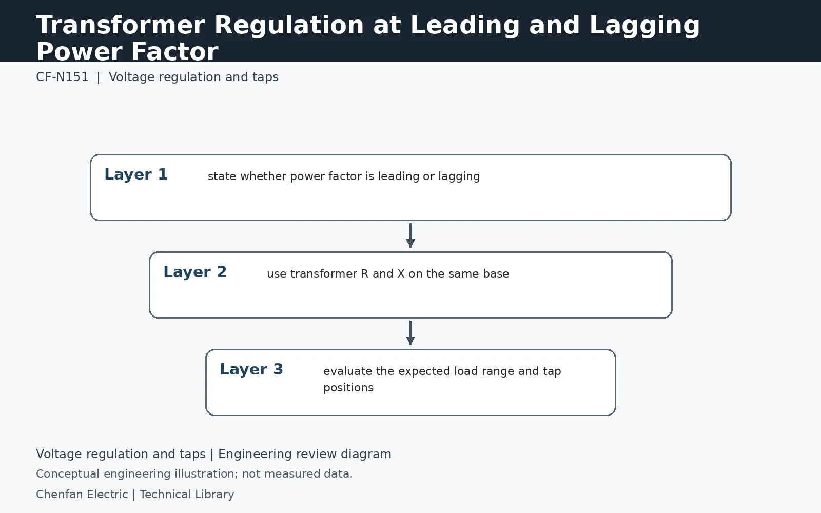
Transformer voltage regulation changes with load current magnitude and angle. With a lagging power factor, the reactive component usually adds to the resistive drop; with a leading power factor, the reactive term can reduce the drop or produce a voltage rise. A useful comparison therefore needs transformer R and X, the actual power factor convention, tap position and load current rather than one generic regulation percentage.
Keep the reactive term’s sign visible
For a small-drop approximation at load fraction k, regulation is approximately k(Rpu cosφ + Xpu sinφ) for lagging current, using positive values for Rpu, Xpu and φ. For leading current, the reactive term changes sign. This approximation neglects higher-order phasor effects and must use a consistent voltage basis. It explains the direction of the change, but a detailed voltage study should solve the full circuit rather than assume a fixed regulation percentage for every load.
The same transformer can show a drop or a rise
Take an illustrative transformer with Rpu = 0.01 and Xpu = 0.06 at rated current. At 0.8 lagging power factor, sinφ = 0.6 and the approximate drop is 0.01 × 0.8 + 0.06 × 0.6 = 4.4%. At 0.8 leading power factor it becomes 0.8% − 3.6% = −2.8%, indicating a rise under this convention. These figures are calculated examples, not performance guarantees or substitutes for the actual tap and network model.
Specify the operating voltage, not just the adjustment target
The transformer drop is only part of the difference between the upstream source and the customer bus. Add source variation, cable impedance and local reactive compensation. A tap chosen to improve full-load lagging voltage may leave an excessive voltage at light load with capacitors connected. The purchase study should therefore retain the source range, load power-factor envelope, tap schedule and the voltage limits at the actual regulated node.
Technical reference framework
[1] IEC 60076-8:1997 — Application guide.
[2] IEC 60214-1:2014 — Tap-changers, Performance requirements and test methods.
[3] IEEE C57.131-2024 — Tap-changers, Performance requirements and test methods.