

A drilled pressboard hole needs dimensional fit, sound entry and exit edges, and a qualified internal wall. Combine gauge results with representative sections and the bearing duty of the actual part. [1]
Calculation basis. Project-specific values and gates in the illustrative screens below are assumptions; cited catalogue values retain their source test conditions.
Start with the hole’s function. A clearance hole around a fastener, a locating pin hole and an oil passage need different evidence. Their relevant dimensions may be similar, but the consequences of wall damage and axis error are not.
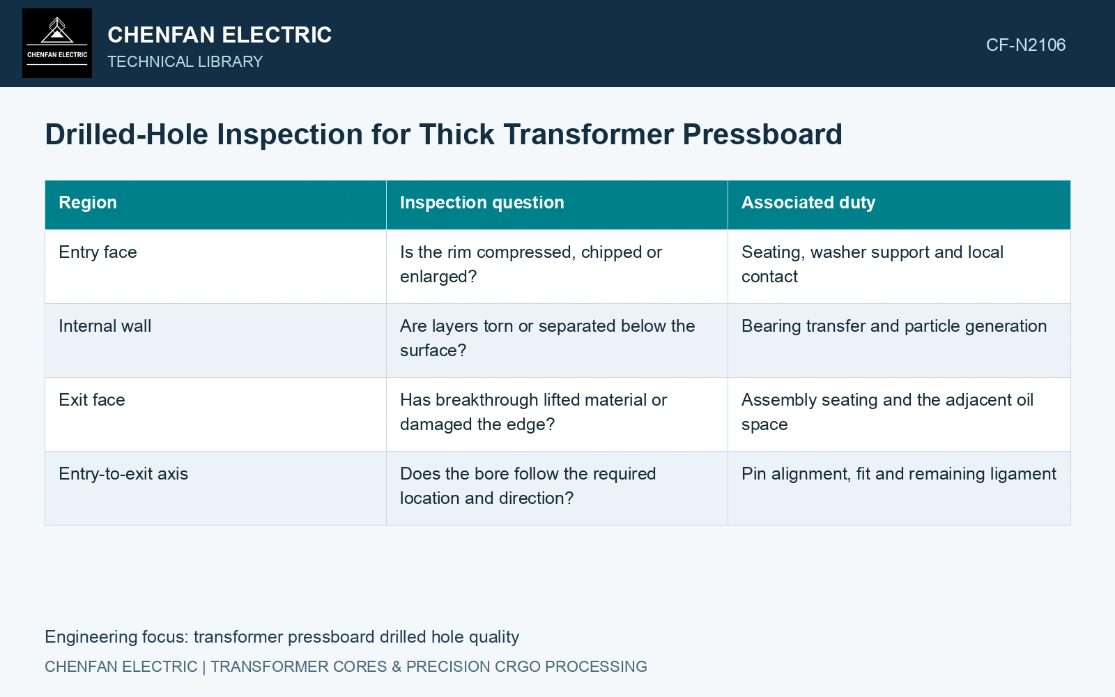
Follow the hole through the thickness
| Region | Inspection question | Associated duty |
|---|---|---|
| Entry face | Is the rim compressed, chipped or enlarged? | Seating, washer support and local contact |
| Internal wall | Are layers torn or separated below the surface? | Bearing transfer and particle generation |
| Exit face | Has breakthrough lifted material or damaged the edge? | Assembly seating and the adjacent oil space |
| Entry-to-exit axis | Does the bore follow the required location and direction? | Pin alignment, fit and remaining ligament |
Measure location from the specified part datums on both faces where accessible. Two acceptable diameters do not prove that their centres lie on the same intended axis. A bore can also wander between them, so an axis check and a representative internal section answer different questions.
For an illustrative straight bore through 20 mm of material, an axis tilt of 0.2 degrees produces a centre shift of 20 tan(0.2°), approximately 0.070 mm. That is only the geometric shift from tilt. Drill wandering, datum error and local wall deformation can add other contributions. No permissible misalignment follows from this example.
Inspect sections for internal-wall damage
Qualification witnesses should include the selected thickness, hole size, edge distance and relevant material orientation. Section through the bore axis and examine entry, wall and exit using a documented method that avoids introducing apparent separation during cutting. Retain the unsectioned photographs for comparison.
A phenolic-bonded pressboard laminate is not interchangeable with an unbonded high-density sheet. Their internal constructions differ, even if both are sold for transformer insulation. The relevant material identity and layer arrangement must accompany a drilling qualification.
For a loaded pin, reproduce the contact and restraint that the design creates. A tensile strip result cannot establish pin-bearing performance, and a neat section alone does not establish strength. For an oil passage, examine detachable residue and blockage in addition to shape.
Keep process observations with the witness results: tool condition, backing arrangement, breakthrough behaviour and part sequence. These records allow a defect at the exit to be distinguished from damage added during later handling. They are not a universal drilling recipe.
Use routine fit and edge checks validated by representative sections. Requalify the internal wall when thickness or construction moves outside that examined range.
Combine bore tilt with the location budget
Retain measurement uncertainty and the actual coordinate decision rule [2].
For the assumed 20 mm bore depth and 0.2° axis tilt, geometric exit shift is 0.06981 mm. Adding an assumed 0.05 mm entrance-position error in the same worst direction gives 0.11981 mm. Against an assumed 0.10 mm exit-position limit, the screen exceeds the budget by 0.01981 mm. Adding an assumed 0.02 mm comparison uncertainty gives a 0.13981 mm upper endpoint, exceeding the same limit by 0.03981 mm. Hold the feature and resolve the tilt, datum chain and internal-wall condition separately.
References
- IEC, IEC 60641-2:2004, Pressboard and presspaper for electrical purposes — Part 2: Methods of tests.
- B. N. Taylor and C. E. Kuyatt, NIST Technical Note 1297, Guidelines for Evaluating and Expressing the Uncertainty of NIST Measurement Results, 1994, sections 5 and 6.